Install a See Level II 709-P3 Tank monitor.
- Split into sections, This page done while doing the install-mostly for my own reference.
- Addressing tank leak issue led to considering new tank level monitor system.
- Justification
- Identifying what may be involved. Parts on order
- Prep and pre wire
- Parts arrived, relocate and wire in new monitor
- Install & wire senders
- Grey sender failed
- Replace failed grey tank sender
Fix leak- eyeballing for new monitor system
-
First, this wasn't planned, though always thought about it- a tank monitor that actually works.
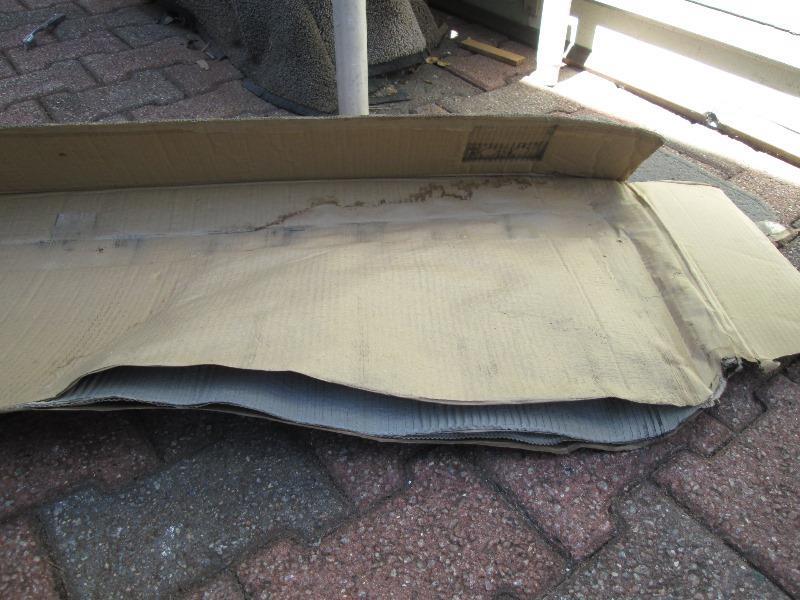
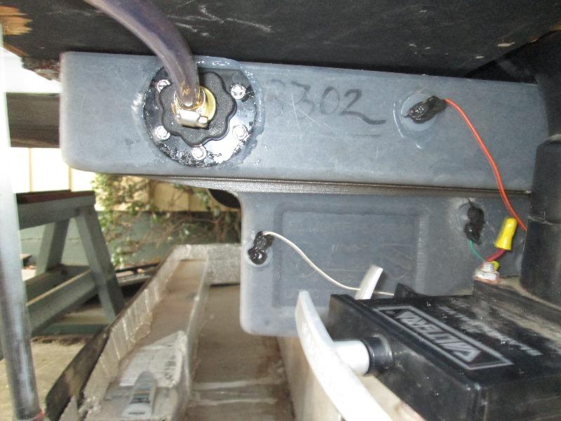
However returning home and off loading camper discovered cardboard that allows rubber bumpers to slide was soaked. Water is dripping out every floor seam. I assumed tank may have cracked as wet as floor was. We hit a rather deep cement gutter, truck leaped. Anyway resigned my self to the task and started prepping to remove tank. Last item is the fill and vent hose to free tank before removing lower section of front exterior wall
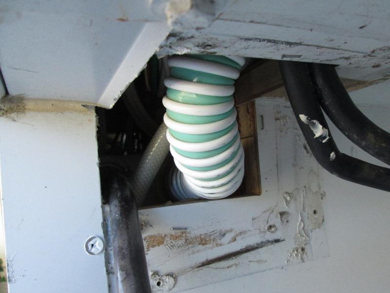
5 minuets from removing the tank, pulled the tin box that gives access to fill hose..it was loose! HOKEY smoke. What I determined was the tank shifted as there isn't any side to side restraint. As it moved the hose caught on the edge of hole and pulled it loose. As the loose hose would spill a lot of water I'm going to hold off pulling tank-its a big deal. Try resetting hose first.
Repositioned the fill hose and replaced the vent tube (it was black inside). Enlarged the hole in wall and added some 2x2 restraints to tank. Refilled the tank 3/4 and went for a long drive, doing everything I could to make water slosh. Once home its bone dry! Whew
Started to button up and though if I was ever to do replacement monitor now would be the time...black has been stuck on 2/3rds for months, and I cut leads on fresh water tank.
Half of the stuff is already apart....so the install begins
Back to the top
Justification
Several reasons for changing the monitor system. The third of a tank readings leave you guessing. IE on a 40 gallon water tank , 2/3 could mean anywhere from 13 gal to 26 gallons left. At 1/3 could be 13 gallons left or almost empty. Black and grey tanks its the opposite. Once they fill to 2/3, don't know if you have 13 gallons left or its time to find dump.We've learned over the years and have only a few times run out of water or had to deploy the auxiliary "poo bucket' to drain tanks a bit. Primarily though its the black and grey tanks. They have never worked dependably except after initially cleaning and rinse. As they age just gets worse. Cleaning will help, but as soon as a piece of anything gets stuck on a sender- readings are inaccurate. Our black has been stuck on 2/3 for quite a while. Serious cleaning may restore- but circumstances and exposing our water tank for other reasons have decided to replace the monitor with a See Level II system.
The See Level monitor reads in percentages 0-100%, though in 4 to 5 increments. Depending on the sender you use, measurements are 3/8" to 1/2" level increments. Still a lot more telltale than 1/3,2/3 or full. Secondly the senders are electronic strips that attach to the outside of tank. They are not affected by random stuff sticking to senders, and give consistent and accurate readings.
Preaching to the choir if you own an RV, But I'm tired of looking down the toilet to see if we need to pack it up. If you haven't heard of the See Level system-worth exploring---
garnetinstruments.com is the manufacturer. Site lists availalbe units and options
Monitor offered with a wide array of functions. Pricing 200 and up. Best retailer I found was .rvupgradestore.com Very helpful folks
The system is very easy and straight forward to install-the work will be attaching the strips to tanks so access and shape of tank will determine how difficult. You need a flat, full height vertical section of tank to attach the self stick senders. Wiring the See Level it uses 1 ground and 1 sender wire that goes to all tanks, verses separate leads from tank to monitor. My install requires running new wire as the existing senders are on side of tank I cant use so need to extend. However the existing wiring can be re-used which really simplifies.
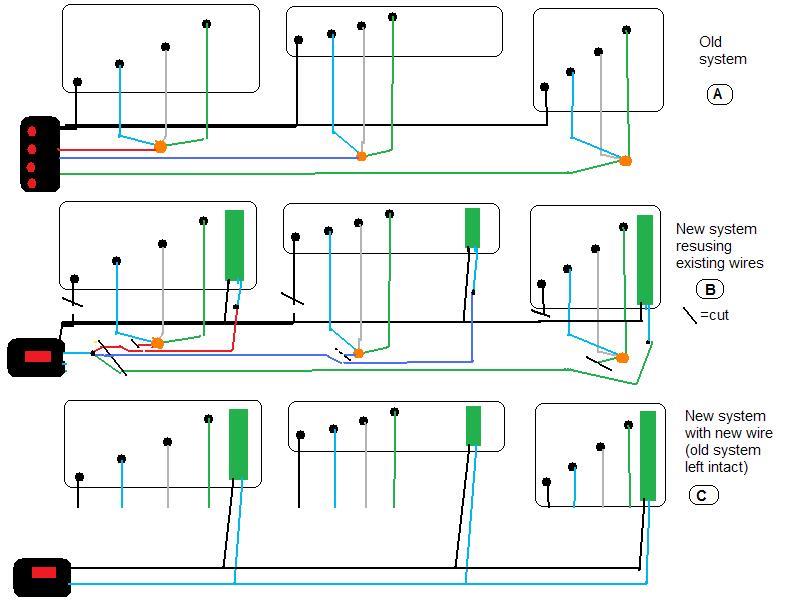
VERY crude cartoon but...
Existing wiring 'A', Reusing wires 'B'. This is the easiest, as wires go from each tank to old sender, Just cut and attach to new senders. I ran new wire "C", left old system intact due to I couldn't access some and would need to splice others. "A" On the old 1/3 read systems, 1 ground and 3 level sender wires (1/3,2/3 & full) are attached to each tank. The 3 level wires are connected together near tank in a 'button' to a single wire then it and ground are run to monitor. This is for each tank.
Cutting the ground and cutting the sender wire after the connector button at each tank, these can be attached to new sender. Note the color of wire that leaves 'button and goes to old monitor. The 3 (or 4) tank sender wires that lead back to old monitor are then cut at old plug (per previously noted colors) bundled together and connected to new monitor with a single wire. Do this for the grounds also.
New monitor uses one sender wire and one ground wire that goes to all tanks. Instead of reading individual tanks thru separate sender wire, it reads all tanks thru one wire and ground. Only the new sender for the monitor tank button you push will respond. Instructions explain how this works (magic) but doesn't really address how to reuse old wires. Will save running new wires thru camper which can be painful.
Some research on which system, and figuring what really going to be involved
As mentioned on mine the black and grey tanks I cant really reuse wires without splicing in extensions. I could tie into wires that lead to monitor and save having to run length of camper. However if I spend the extra hour (or 3) I can leave existing tank senders and wiring intact. Also connector at old monitor intact. Allow reusing old system if needed. Mostly though it makes sense to me, other than time to just run new wire directly to new monitor.
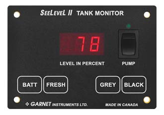
System I chose is the 709-P3-1003. Has indicator for Battery, Fresh, Grey & Black. Has a 3 way switch for water pump. They can be had in several configurations switches etc.
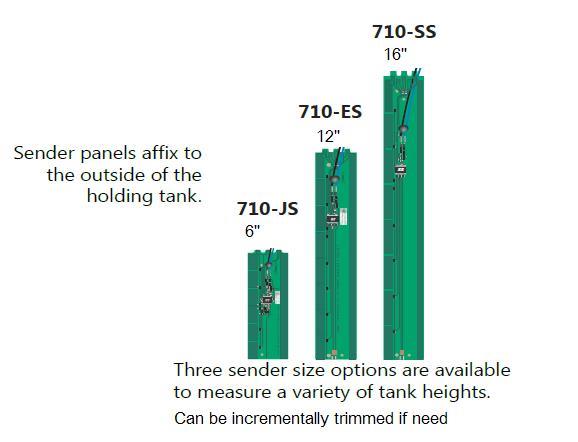
3) 12" ES senders are included but 6" or 16" can be substituted to closer match tank heights. They are trim able to a degree. Im using a 16"SS for 18" tall fresh tank , a 6" JS for 7 1/4" tall black and a 12"ES cut for 8 1/2" tall grey tank.
The new monitor will be mounted in place of existing tank heater switch, hole needs to be enlarged to 3� wide by 1 7/8� tall. The existing (previously added 3-way) water pump switch will be removed as new monitor has one, its wiring will transfer over. The existing monitor will be removed by simply unplugging and its plug left in hole in case I ever want to reinstall.
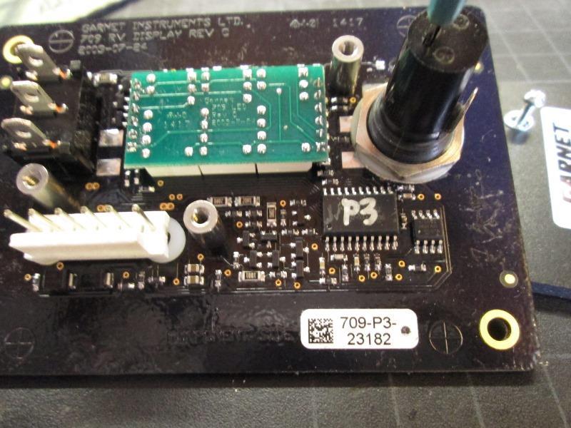
(Picture of old monitor for future ref if needed)
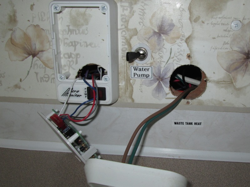
The tank heater switched will be mounted to cover old monitor hole. This wall is hollow so moving wires, swapping panels will be easy. Getting new wires up from under sink a bit more effort. IF I were reusing old wires I would cut & tie the red, blue and grey wires, and attach to new panel with one wire. Reuse ground.
Ill point out behind the wall is quite a rats nest. There are 3 4-wire cables coming from individual tanks that are cut and spliced to what's visible, plus power and ground.
Swapping positions be Nice as this will move monitor out a bit and be a little easier to reach. Old one tucked back in corner wasn't.
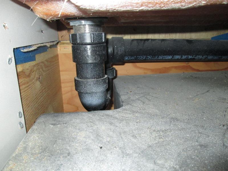
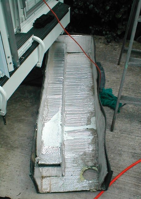
Our black tank. It is captured on all 4 sides within walls. Only this notch is usable to attach sender. There is an access panel below but unsure if I can remove easily. Otherwise Ill pull the P-trap to clean tank and attach sender.
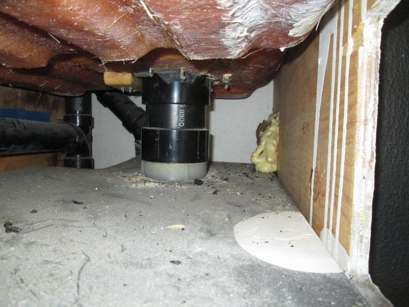
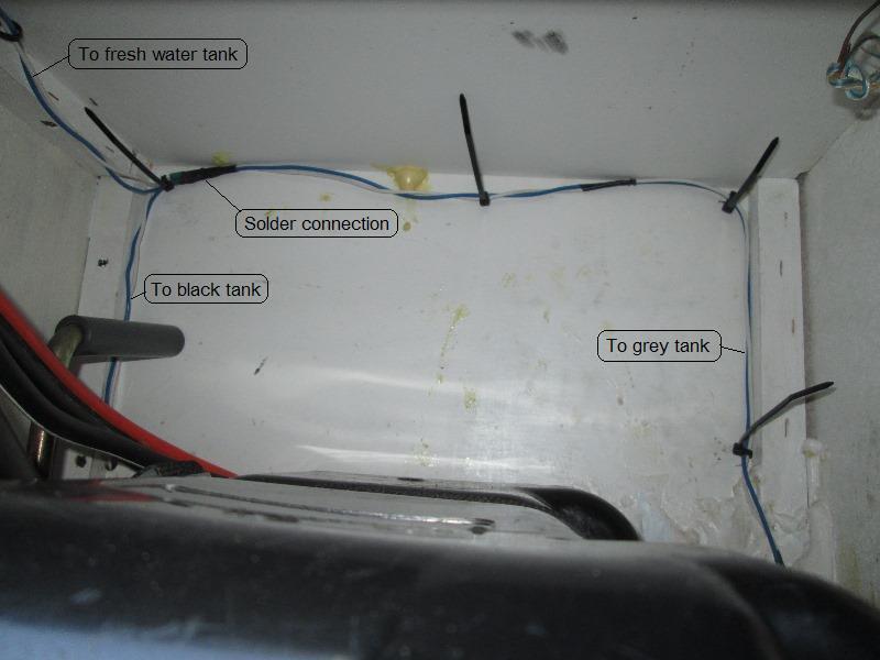
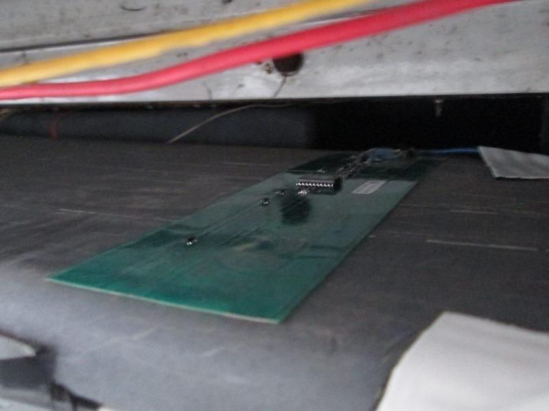
This is looking over black to rear of camper. At the back wall are the original senders-totally inaccessible. I'll run my new wire from front notch of black tank to back and thru the wall where foam is. That's the into valve compartment. The grey tank which is under black tank but sets width wise behind bumper, is open to valve compartment. So wire from both tanks will exit into valve compartment
Grey tank that's in front of bumper, cant see much. I've already removed a plastic tray that covers this. Should be pretty simple to clean and attach. Wire will run straight back into valve cabinet as mentioned. Only issue as this is semi exposed to elements need to add some protection, maybe. 3M Professional Grade Rubberized Undercoating, product code 03584 is recommend. Though couldn't access to spray after installed...more thought required.
Looking at these pictures of black and grey tanks I understand why rinsing totally ineffective-especially the grey. Both the drain lines into tank and the outlets are on same end of tanks. Rinse water from toilet or down sinks just passes out never reaching opposite end of tank. Grey has always been a problem with reeking, worse than the black. Think I need to invest in some tank mounted nozzles at ends of tanks.
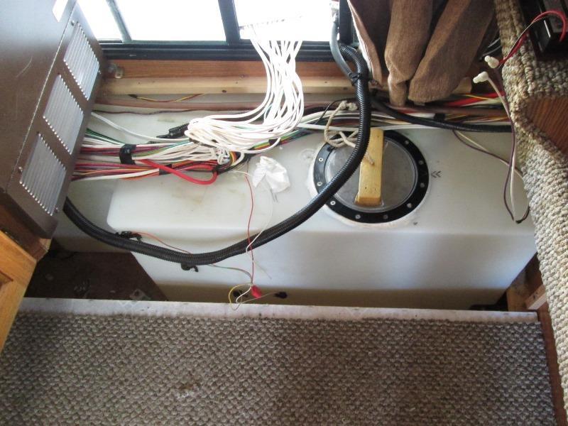
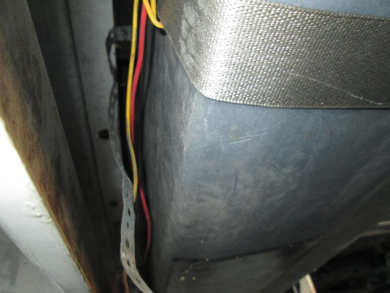
And this is fresh water tank. A breeze. Wires from rear tanks will run up in here. Connect all together, then snake the wire from monitor down and connect.
Prewire: enough eyeballin
Picked up 2) 40' rolls of 18ga, blue and white wire.
Pre wire black & grey tanks into valve compartment- right to left- grey, black, and feed to freshwater box. These 3 leads will be tied together.
...at a pause-reconsidering if I really want to run new feed all the way to front...new wire is pushed up into cabinet under bath sink. To get from bath to front will take couple of hours.The existing wires are laying in bottom -I could cut and splice into them and forgo the effort....hmmm
.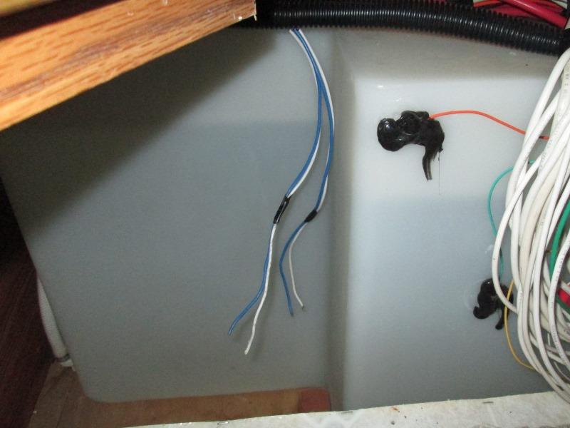
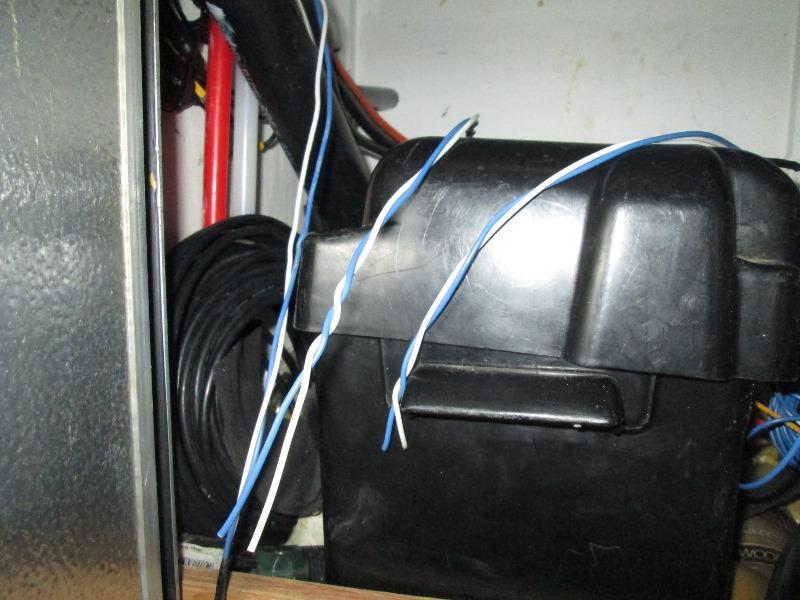
Sticking with the plan..Fresh water tank compartment. Wire from black and grey tank, and wires from monitor location run to water tank box. Pre wire is done. Literally 4 hours, several scrapes and a lot of crying to my self. I hate running wires in the camper-just a major pain. . Wires from valve compartment up into bath cabinet, behind closet then stove under kitchen sink to fresh water tank only took an hour and wasn't too bad. The wire from monitor location down to water tank took almost 2 hours.
Leads solder together. Loosely zip tied until final tank sender connections made. Picture mostly to document what's what
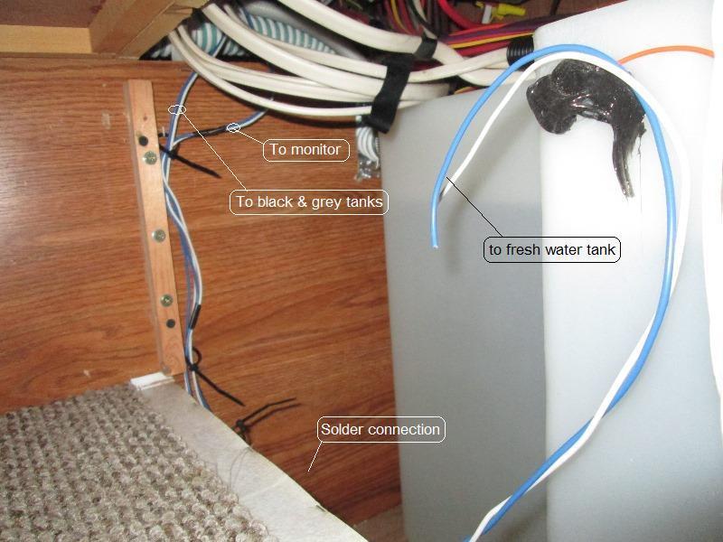
And wire from black & grey soldered to lead to monitor and added branch wires for fresh water sender. I will add labels to wires wire they go up into cabinet in case I need to identify later which is which, and at rear valve box.
Prepping for the monitor.
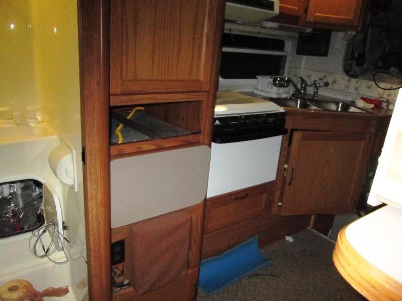
All of the wiring on back splash go thru wall into back side of a drawer cabinet in cab over bed area, then down thru the cab over floor and back thru wall to under sink. Convoluted to say the least. Access is reaching back thru drawer face almost 2 feet. However prior to me having done some wiring that go thru cabinet and defeating ease of removal, (speakers, inverter/shore receptacle, TV patch cords and other stuff) 2 screws thru back splash and 2 screws thru front face to wall and the cabinet easily came out to access the wires.
Just in case your also working on a '01 Fleetwood Elkhorn camper :)
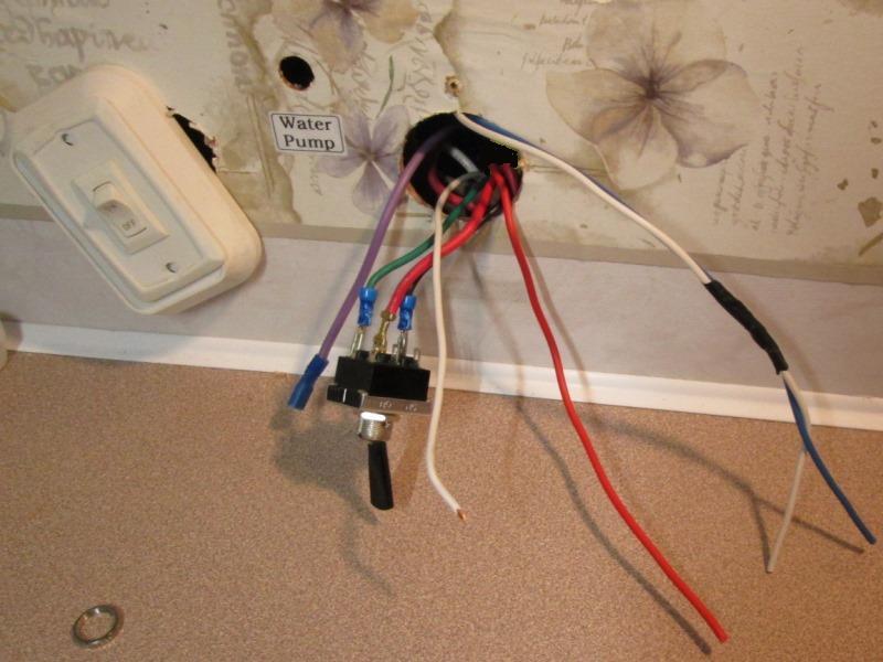
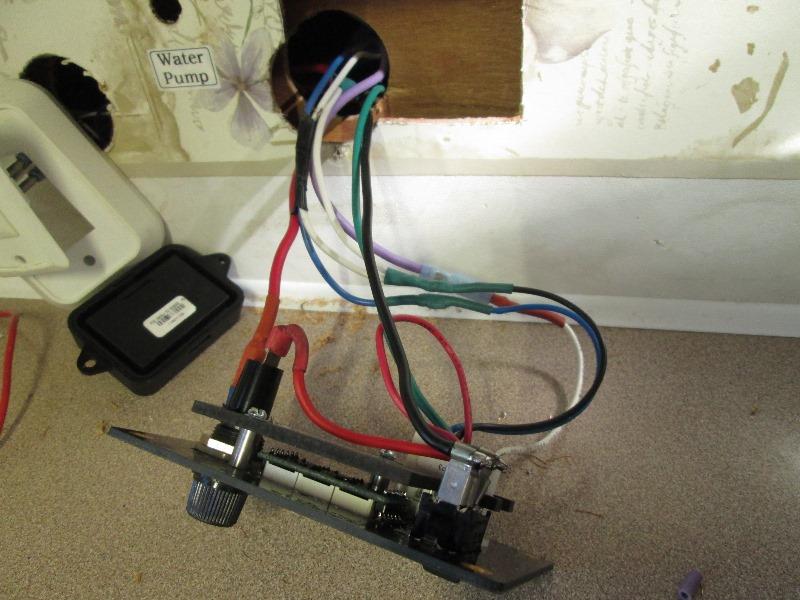
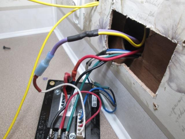
Moved the existing switch tank heater switch to cover original monitor hole. Tapped power and ground for new monitor, power is separate fused circuit from panel. Remove the 3-way water pump switch and push thru monitor hole-its wires will get transferred to new monitor pump switch. And the blue & white wire that goes to all tanks. The purple wire is from pump (originally was pump feed) it only acts as pilot light feed now. I may or may not need it-unsure how new monitor pump pilot is triggered or if it has one. If it doesn't have pilot I'll add a pilot in old switch hole. Otherwise need a plug to cover hole as I want to place monitor as far to the right and still cover large hole.
Um after the fact-monitor/water pump circuit is on same circuit as stove vent and lights, 10amp fuse. Instructions state 7.5 for new monitor. Hopefully monitors pilot will work and I can use the old pump switch hole for a panel mount fuse holder to separate it from the rest of circuit with smaller fuse. ...
Waiting for system to be delivered. All that's left is cut wall for monitor. Wire in new monitor. a bit of soldering to connect all the tank feed branch wires to senders, glue on sensors.....(after temporality taping in place to verify vertical placement). -anxious.
Parts have arrived, wire in monitor
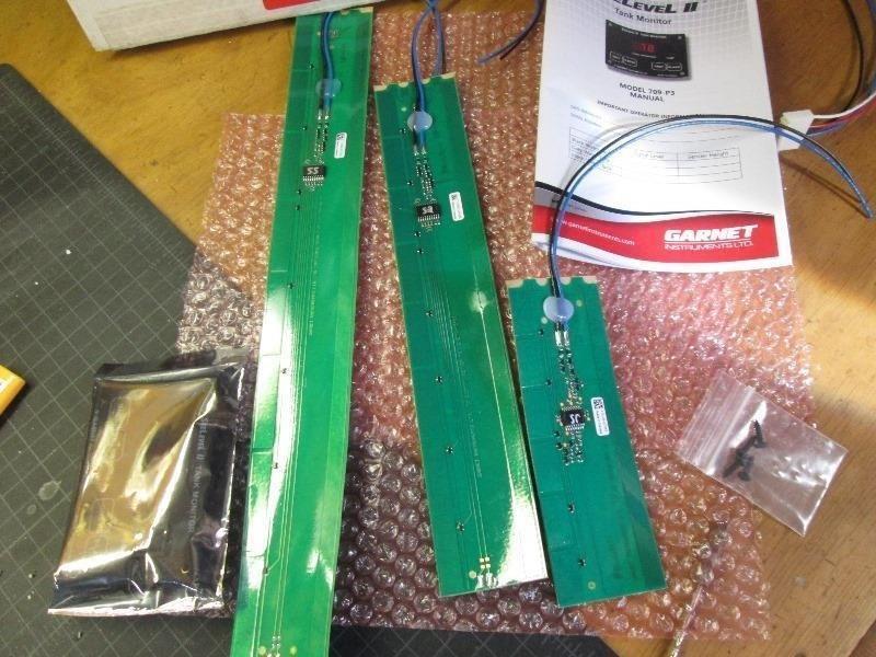
Nice. Monitor is in anti static back. 6" 12" & 16" senders. Note the bag of black screws to mount monitor, this is the last time I saw them. The sender strips are semi rigid, I'll only need to cut the 12".
First order of business is to mount monitor, get it operational to read senders. Means deciding where & how to add a 7.5 amp fuse, circuit is 10 amp . As mentioned my thought was using the hole old pump switch was in. But looking at monitor however I notice board is cut for optional switch. Printed sticker on front covers it.
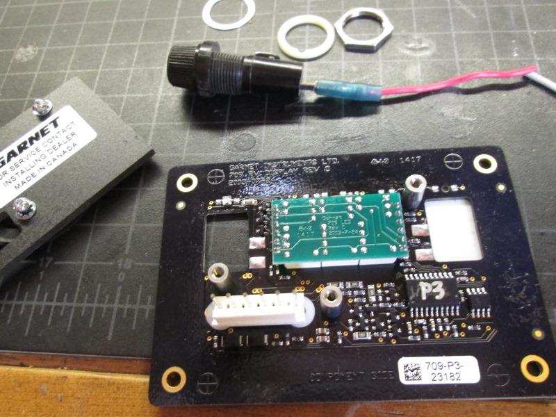
Means I could add fuse holder to board in that hole, limiting amps it and pump see to 7.5amp without something else stuck on wall. Cool, if I can do without ruining. Removed the protecting back plate, and 3-way pump switch to help size hole I need to cut. As there are not any traces or electronic stuff outside of switch hole I can enlarge to accept old holder. Note some of the monitors the pump switch is hard wired into board. On this one, 709-P3, switch is independent of board, which for our use is perfect. Dug thru old parts and picked fuse holder with larger body that has no existing anti rotation flat. It also has screw in cap verse push & twist.
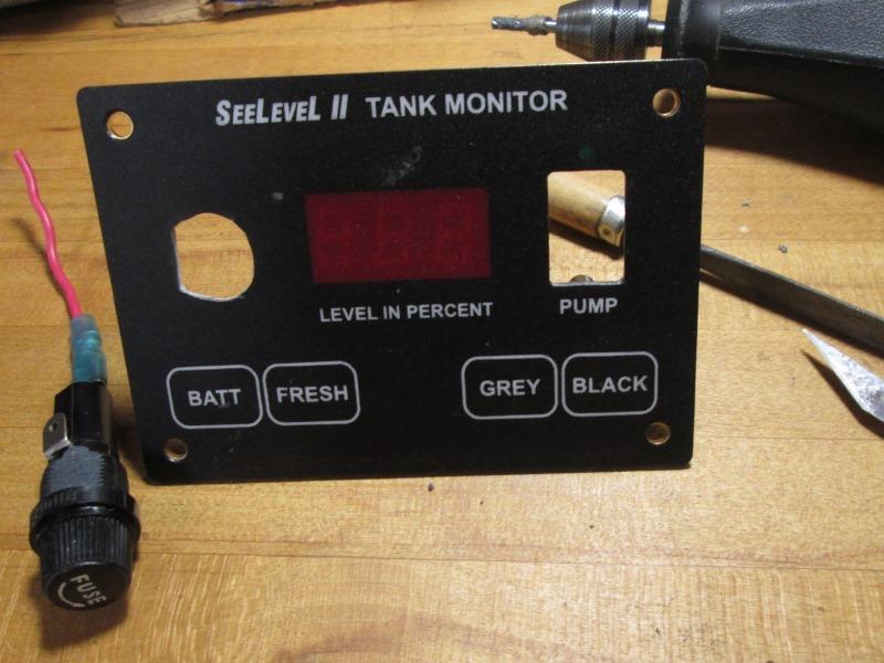
With fuse installed and cap screwed in, filed a flat on body to orient it in panel. With Dremel, X-acto and small file carefully and incrementally shaped hole until holder just fit. Slightly enlarger toward out side edge.
Large nylon washer under lightly snugged down.
Used flag terminals to connect the pump switch and fuse holder, solder monitor harness leads and added bullet connectors to lead FROM pump. So everything will unplug if removal needed. Note- white wire on monitor harness is labeled 'pump indicator'. It is what activates the pilot light on board. This isn't described in instructions. It is simply connected to a lead that is hot when pump is turned on, either to out lead of switch if used as on/off-single switch, or in my case from pump as I have 2 3-way switches, one here and one in bath. Fortunately hole thru wall into cabinet on other side where wires come from allows fuse holder to pass as I only have 1" thick interior walls. Garnet does sell gaskets if mounting on metal surface, and larger back plates if hole in wall larger than monitor, but they do not sell a box so monitor could be surface mounted.
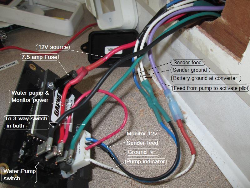
Documenting wires. Note monitor and sender grounds both tied to same chassis ground. Plug on pump indicator wire is allowance to add external pilot lamp.
update 1 1/2 year later 05/19 for FMI- just added pic of wire added to purple water pump pilot wire, yellow to feed new momentary switch to activate circulating pump in bath.
Update switch addtion listed at bottom of page, using hole left over from this install 10/17
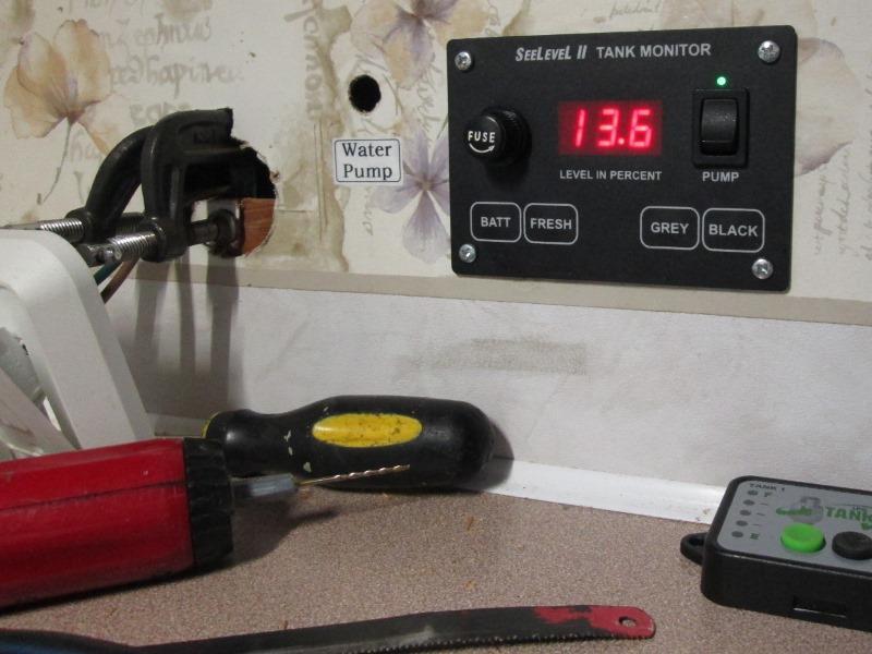
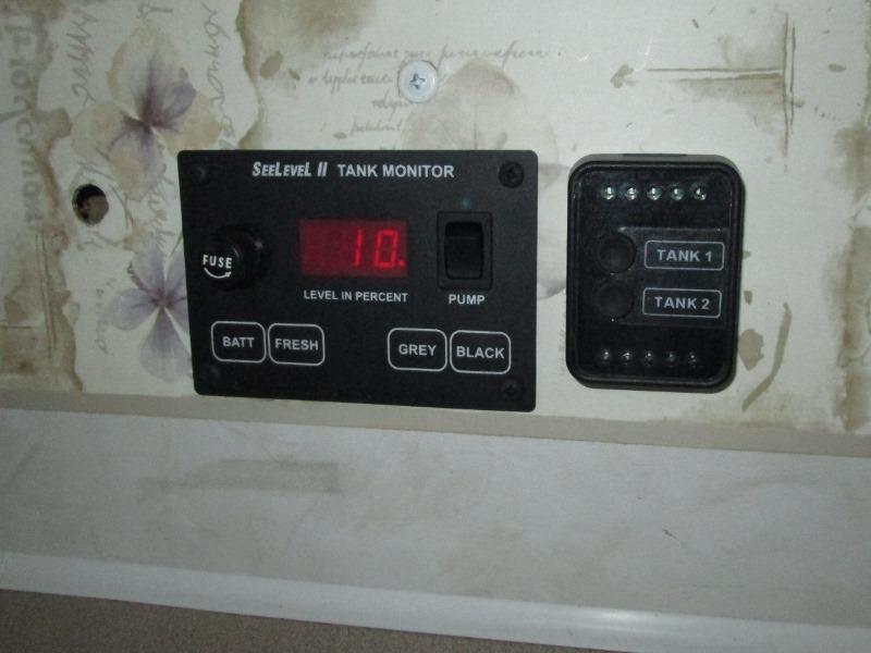
Not too shabby- easier to access, use and read. Green or blue digital readout sure would have been nice. Steel screws-next trip to hardware pick up some painted screws. Had to glue in backer to install the moved heat switch. On to the senders
Sender wiring and install
Instructions do state you only get one chance to apply...let me restate-you only get one chance. I started with the fresh water tank as its open and easy to access. Getting it aligned where I wanted top touched and literally tank grabbed the sender. 2" stuck, tried to gently free and it wasn't happening. Closer to top than planned but no help for it ran it down and hoped ok. Solder and shrink wrapped the connection before sticking sender to tank.
It actually worked. Luckily. A little crooked but close enough. Hard to see but lower water line is right at end of sender, monitor says 4%. Perfect as it's also just barley above pump outlet. If placed where I thought it should go pump would have been sucking air and sender would have still registered water. On the water tank error to placing higher.
Knowing HOW sticky senders are spent a few more minuets placing sender before peeling off backing.
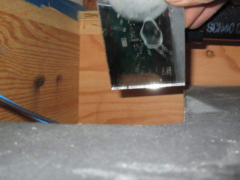
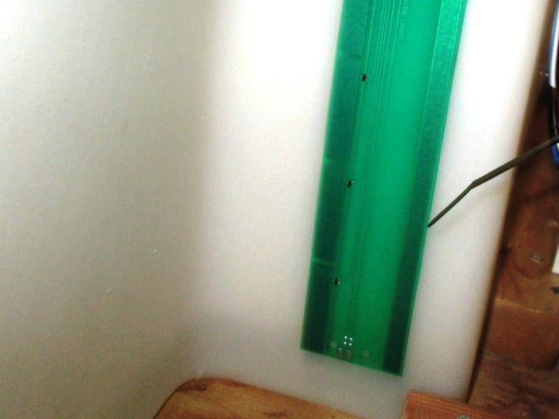
Black tank done. Picture doesn't show but old mirror verified placement, 6" sender on 7 1/4" tank is about centered, slightly closer to bottom. I removed the shower P-trap that goes to grey tank for easier access to black tank.
Grey tank, working between bumper and tank, sender ended up almost flush to top. Though I had to lean to placing higher than should be due to curve at bottom of tank. Hopefully will read close to full before coming up in shower... but wont know till we fill it.
Went back on all the tanks and used some scrap eternabond tape to secure wires. Routed and zipped tied in place. Gorilla duct tape is what's used by many.
Put some water into tanks to test level and see monitor register. Whoo!whoo! Its working. Reading in 4% and 5% increments just stoked seeing level changes with only gallons verses 1/3 of tank.
Fresh water is ideal-, registers 0% (empty) with just a slight amount left before pump runs dry. Black also good though opposite, reads full and looking down toilet its just under top. Grey , cant tell, cant see. I also still have the shower drain to reconnect so wasn't pushing my luck to overfill. It is registering on monitor. Once buttoned up need to drain then fill to see what it reads.
Fresh water you want to lean toward placing senders higher as you want it to read zero% before it actually does-100% or full not so critical. On holding tanks the opposite, lean toward closer to bottom so they read full or 100% before it actually is. DO make the extra effort and temporarily tape senders to tank, check readings. Once stuck on there is no way to adjust
Kinda bummed with placement of grey sender-nothing I can do though, short of buying another and try again.....
or just wait and see.
I had installed a tank rinser while grey tank was exposed. Needless to say it leaked and I had to rework. A bit later added one to the black tank. Both moved to separate page.
Modify grey tank cover. Section of aluminum insulation needs to be removed where in front of sender and a bit of the bottom. Cut a 6" wide strip, replace with some plastic bubble wrap. Quite a struggle to get the cover back on but were almost done.
Got everything buttoned up. checked level in grey tank because I was putting a lot of water in it when reworking rinser... monitor says open circuit- good grief..I was done.
FAIL
System was working awesome- Means I either cut a wire putting the cover back on or something when coating the sender or?. Crap... Tomorrow I'll pull the cover back off. Hopefully find a cut wire, simple fix....so close-not a happy camper at the moment.
Remove the tank cover, no wires cut, dang. Monitor still shows open. Possibly wire broke internally just not visible, started testing.
Per trouble shooting guide, shorting the wires going to sender monitor should show 'Sht', means wiring is good, Did this starting in valve compartment box, and a few places along the length until I was at the connections of sender board. Monitor shows short at each step. Means my wiring is ok up to sender-so its the sender.
I had contacted Garnett. It was suggested possible fault is the trimming of sender tab, that 'programs' it , is not complete or shorting reestablishing electrical path. If so, sender would read as fresh water sender, cant be 2 senders reading as same function and since fresh is showing error, sounded likely.. Problem is unless you can reach top of sender to re trim cut tab-kinda stuck, I cant'. I didn't think this was the case as it was working, but to verify if I removed the sender, recut the tab it would tell me that was the problem. Garnet agreed but said the sender would likely fail taking it off or long term be unreliable and they would just send a new one. I wanted to know WHY sender quit so using a heat gun and couple of putty knifes, removed the sender with out bending it. It needed to come off anyway-. Once off, cleaned the top, looked fine but recut the tab. The error on the fresh water tank went away but grey still shows open-so indeed sender is bad.
( NOTE: unrelated to failure but we had another issue we were unaware of, erroneous info from grey sender. We saw numbers so assumed it was working not knowing how much water was in tank. But the insulated/protective cover on grey tank was interfering with sender. It wasn't until later we figured this out.)
Replacement is being shipped. Why it worked and why it failed a mystery. I didn't cut wire with cover, system was de energized and wasn't used until done. Needless to say, I'll take opportunity to more correctly locate, Ill be more careful putting cover back. I'll also be testing at every step on reinstall of new sender-if it fails at least I'll know when/what caused it. 3 days to wait.
I will pass on. With a failed 'Opn' sender, that it can cause other monitor readings to show 'Err'. In my case fresh water. Cutting the bad sender wires the monitor still shows 'Open' for that tank but the error on other tank goes away. Point is- my original thought of using a terminal block to make connections between tanks, instead of soldering or butt connector, would allow removing a sender without cutting wires in case of failed sender or testing. I had decided not worth the effort but now, I'm wishing, going back terminate all wires with ring terminals. Then I could easily remove a bad sender from loop and only have one tank not reading instead of 2.
Only good thing in this episode is I was amazed with the function of the error codes in isolating and determining problem. More so with Garnets willingness to help diagnose.
Replacement sender arrived
No pics-just installed. Went to great length to temporarily tape in place, with wires just twisted together. Got a line marked at bottom of tank & sender with monitor showing 5-10% @ �1/2 gallon. Error to the monitor reading full before it is, last attempt it ended up all the way to top would have never shown full. Removed the sender. Ran a full length piece of Gorilla tape covering sender face and holding wires. Once mounted plan is to cover horizontal with overlapping strip to seal sender to tank. Again ours is semi exposed, needs some protection.Peeled the backing off the sticky side. Sliding my hand up 3" gap to place sender, with what looked like even with the line I made started to stick bottom. DOH! Its about 3/16" lower, Tried to gently pull loose-that ain't happening, only about a 1/2" stuck but I'm not risking sender. Went ahead and glued it down. Checked the monitor-it still shows 10%.Whew
Resolder the leads and shrink wrap- check the monitor again.
Ran several 6" strips of the Gorilla tape, overlapped half width starting at bottom and running over top of tank. Pretty confident sender should stay dry. Recheck the monitor. Taped the wires out of harms way and ran another vertical strip on sender to ensure cover doesn't snag pushing it up. Checked the monitor again. Replaced the tank cover and its 2 dozen screws. All that's left is some minor caulking and touch up the undercoating on lower box. Checked the monitor one last time before I pack it up ....
Its showing 20%? Drained the grey tank, only 2 gallons in it- Monitor still shows 20% - empty. Cant win.
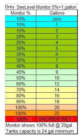
Decided to manually check tank and what monitor shows. With the tank empty preceded to refill dumping 2 gal pail into kitchen sink-watching monitor and writing down % and gallons. 26 gal capacity so 13 gal would be 50%, monitor reached 50% at 9 gal. Recorded % with each 2 gal, then 1 gal noting what monitor said when half full. Filled up rest of the way until monitor showed 100% which was 19 gal. Decided to go ahead and continue adding water to reach 26 gal. However when I hit 22 gal water came up in shower. Drained off almost 5 gal before monitor showed 95%. Added back a gal to hit 100%. Did this several times. There's about a gal discrepancy when filling or draining? However 100% is about 4gal from coming up in shower. Given the amount of pipe closer to 3 from actual tank full. The 50% / 9 gal is half of the 100% @ 19 ga.
Also between empty and adding 2 gallon only raise 5 %. Monitor of grey sender measure in 5%increment. What Im concluding is empty really isn't. Cant see drain outlet but must be slightly above tank bottom. Having a hard time believing capacity is 4 gal shy, 22 verse stated 26. Sender is low so cant read empty because there is some water left, Full leaves 4 gal but that's spread over 12" x 5' roughly area. Looking at picks of old sender full (and we've never had water come up in shower) kinda think that we've more than likely have been using the tank at about 20gal capacity. Thinking also that when monitor shows 100% tank is more full gallon wise than when old monitor showed full. Dime against a dollar fill tank to 100% with new monitor I bet we have water sloshing up in shower....
So Im relaxing a bit. Don't care about how empty, only how much is left. Last note after doing all this and draining tank- empty now shows 15%?.
So grey just turned into a pain, got 1st sender mounted too high then it failed. Replacement could have fixed height but ended up mounting too low. Then realized cover affecting sender. Its measuring, just off-I could by spending more money and effort, replace and try again- Pretty sure I'd use a 6" though, placement just to critical with the cut 12". Also mount with tank filled less 2 gallons, so full would show with some reserve, then drain to see empty. What I should have done in the first and second place. Live and learn.
Install concluded FAIL 2 not system but grey tank cover interfering with readings.
And it all changed. Went out next morning, grey tank bone dry showing 30%! Pour some water down drain it jumps down to 15%? Determined, and should have obvious a lot sooner, it has to be the aluminum lined cover the way its jumping. Dropped it and monitor showed zero%, pour in 1/2 gal of water jumps to 10%. Slide cover up, it up jumps to 20-30%. I had removed section of the aluminum bubble insulation near sender but took out another 12" section. Down to 15-20%. Kept chiseling away, removing and reinstalling cover half a dozen times. Ended completely removing the foil bubble wrap. Tank empty now reads at a consistent 10%, which partially is because sender too low. The cover itself (plastic box) is interfering a bit but it has to be reinstalled. Certainly better than the jumping up to 30%- Wait and see before I get to excited.Major pain but if sender hadn't failed would be living with empty tank reading 30%-jumping around. I don't understand why the plastic box though is causing such grief, likely recycled material contaminated. Biggest grip is this had to all happen on the grey tank which is a major pain to work on, Its also the only tank cant visually confirm levels.
With a start point of 10% previous measurement no longer valid. Going to repeat process, measuring actual volume against percentage. The New See Level system, even given ordeal of grey tank is awesome.
Measure it out again, bit better, draining also by 2 gallons drained off 16 gal-monitor showed 55%. Due to monitor doesn't show last 4+ gallons when filling. But as mentioned that last 4 gallon likely slosh into shower. So either dump, leave or use the Poo bucket. Easily get an extra day or better once it hits 100%- its just you cant tell how much past 20 gal we are. Should note rarely do we fill the grey unless using shower.
So we are good. Consistent readings from the grey tank. Off a bit, just never shows empty, but consistent and reliable once it starts filling. IF I could remove or find something to replace the cover, grey would read accurately. It is slightly possible that replacing sender and raising it 'might' compensate for the 10% cover adds when empty , not sure worthwhile. Not sure due to lack of access if I could place in a more optimum location. If I get a wild hair.
Back to the top
WHOO WHOO!
Just stoked, snafus aside.
Now that its done- the See Level II system is just nice. Our 2 critical reads are fresh water and black which work flawlessly. Grey is off a bit due to installer error and plastic tank cover interfering but its close enough to KNOW instead of guessing what is in the tank. Battery readout just a bonus. The included 3-way pump switch tidied up previous install. I highly recommend this system. Failure on install-well its going to happen sometimes, just happened to be my turn. I honestly assume it was something I did.
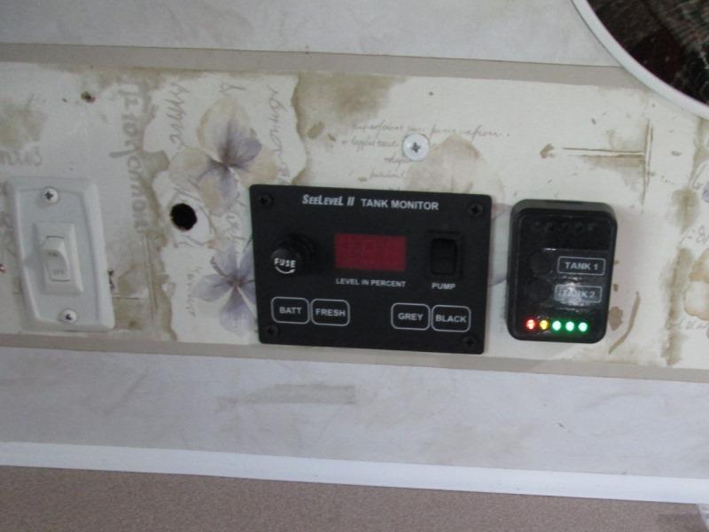
Shown is finished mounting and installed Mopeka LPG tank gauge done a bit later next to the See Level monitor. It was going to cover old switch hole but placed where easier to get to. Remounted tank heater switch less its surface mount box. Just need a plug for unused hole -another project.
Update 05/19, year and a half later...Add circulating pump switch in hole, mostly to fill hole but activates circulating pump in bath.
Related-done at same time
Install Black & Grey Tank rinsers
Add LPG monitor for tanks
Back to Ourelkhorn Camper Modifications page