Add refrigerator cooling fans
Note this page is more for my own documentation than anything else/ quite long as I kept adding to it. You may find some useful information as to why & what I did, or not. If only using some of the links provided you may gain understanding of your refer- how the drafting in the back affects cooling.Also just FYI; generally our fridge has capacity of about 40degree cooling lower then ambient temp. The freezer section is designed to be 30 degrees cooler than lower box. So If its 100+ outside unaided lower box easily could see 60, freezer 30. You'll note most state freezer is still cold but main box gets warm. And like us worse as the day goes by. We see inside refer climb in the evening but outside temps dropping. I can only guess due to heat saturation of insulation walls etc. Thermometers that have probe embedded in something give you a better idea of items in refer-monitoring the air just causes grief...
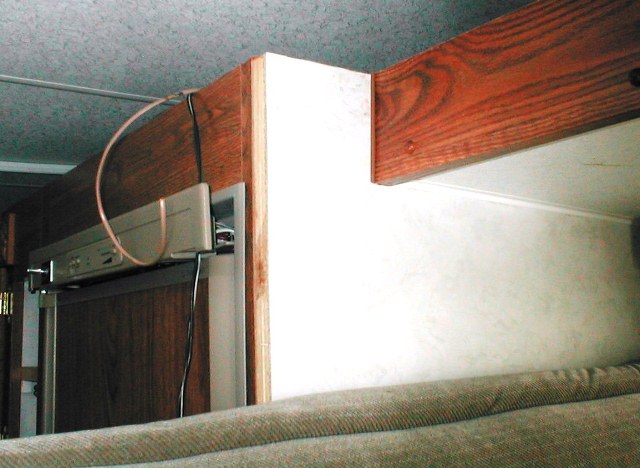
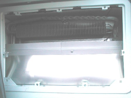
The refrigerator in our camper has never worked all that well. Works to stay in the mid 40s. I have thought for years that Id like to try adding a fan outside the box. Just never did. A recent post on the RV.net forum fella with a pop top was installing a refrigerator in place of ice box. He was asking about the venting/clearances as he would be using side vents. I went and took some pictures of ours, looking down the upper vent to show where chimney stopped from upper vent opening...I saw a fan! Wow even when I had run wires up the wall and over the top of refer on past project-just never stuck my head in there. Fan is located half between upper * lower side vents. Cool i have a fan-guess I don't need another.
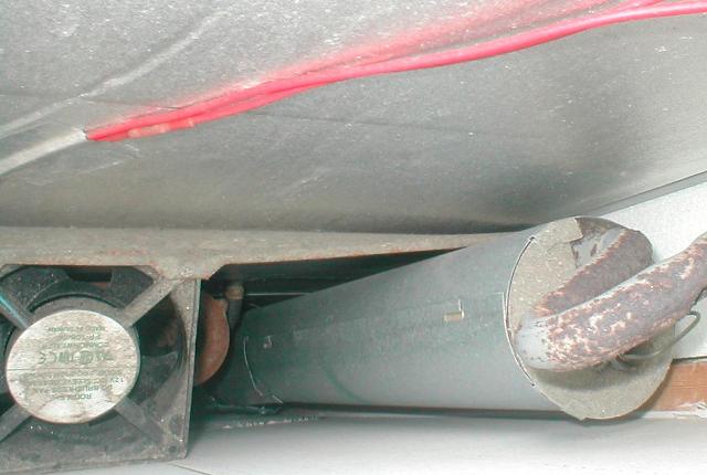
Looking down the upper vent discovered fan
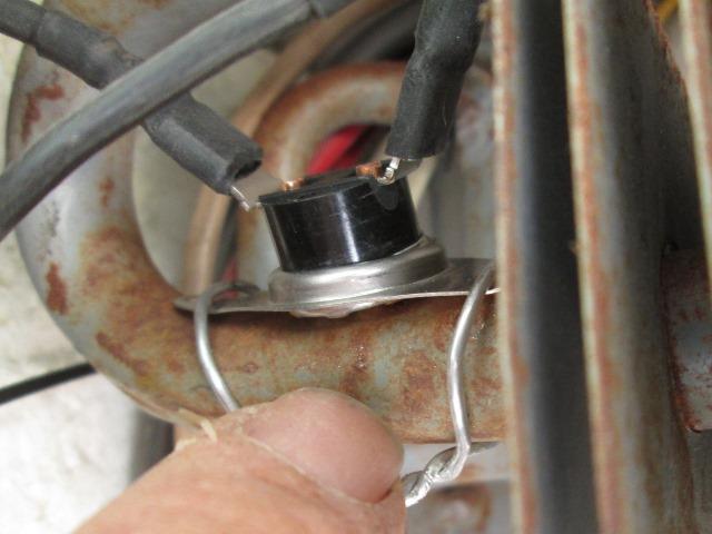
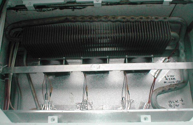
But in the back of my mind the fan puzzled me. If I have a fan, why don't I see temps that other see. Then in another post where a fan was added but closer to the cooling fins and some others posting there mods and results, I decided to go look at ours. Out of curiosity I wanted to see/verify that fan works. On the fins 12v feed goes thru a thermo disk, then to fans. Fan comes on when refer reaches a certain temp. I hooked up jumper bypassing thermo disk, fan didn't come on. Turned on refer, fan came on. So fridge has to be on and thermo disk closed. Wow that fan is loud. I have never heard that since we've owned camper. Bad thermo disk? Set too high.
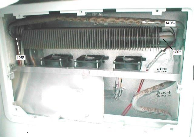
Went back to the thread about cooling the fridge see if any info on thermo disk. Following discussion about the air movement and how its supposed to work. I visited link to RVmoblie site, article has some basic information that explains how our 'absorbtion' refrigerator works, but more importantly how it vents. Its a main part of the cooling process, its also the main area where installers/camper designers error, by design our side vent are the worst. Basically the hot air rising at back of refer should flow thru the condenser fins at top and out vent.This evacuates the ambient hot air but as it passes thru condenser the rising air also dissipates the heat thru condenser cooling fins.
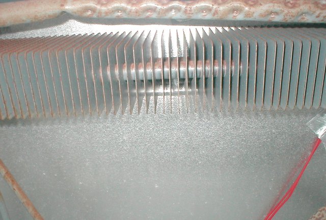
Condenser fins located at top of refrigerator
With our side mount refer vent and the condenser at very top against fridge, any rising air will simply go out vent, no reason to pass thru fins. Part of the design is that the outer wall should be 1/2 from fins to force air thru fins. Our is 4" plus fins are above vent opening. This is where most are deficient. to much gap. Second would be design of box, just gets hot behind refer, forcing it to work harder. I did identify our factory thermo disk as 158°, way too high to be off any benefit.
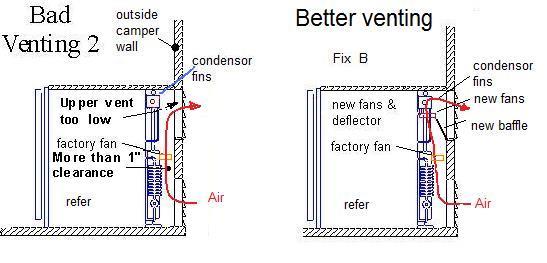
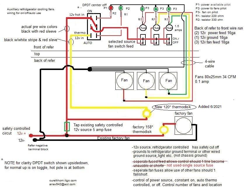
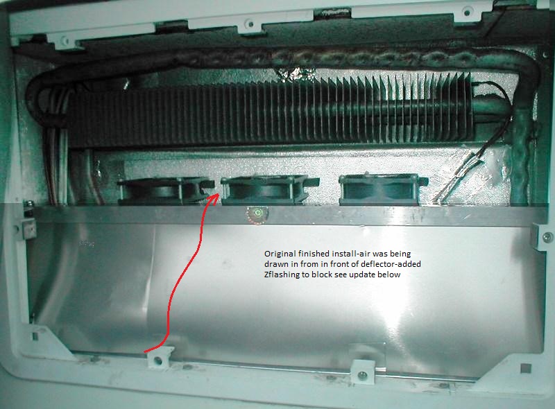
Heres a diagram of my stock setup and my new one.
If your fridge wont keep up when its hot or just curious visit this thread at RV.net to see discussion and study this article at RVmobile.com (link no longer valid). Worth the effort to gain an understanding of what might be beneficial. If you camp high heat-refer wont keep up, this might help you decided if a worthwhile project. It would also help following th links to decide if your refer box was poorly executed, and could use some TLC.
Another resource is Dometic http://webspace.webring.com/people/jv/vintage_campers1/Dometic_Refr_Service_Manual.pdf
So that's how I got here. I'm positive it will help. Adding the lower thermo will make factory fan come on sooner should ambient temp to get too high. Adding the baffle, which should increase the passive effect of rising air to cool the fins, and adding fans that will insure air passe thru fins and force air out top vent. .
- On too the install...1st my plan.
B. Change 158° thermo disk with 120°. Higher than new fans due to higher amp draw,. want it on last. haven't ordered yet-still debating temp
C... Add new fans. Requires building some sort of mount. These will run thru a 100 ° thermo button (again not ordered yet).
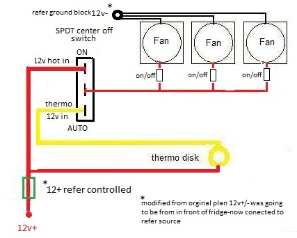
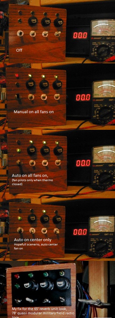
D..... Wiring : I'm adding an SPDT with center off switch, I will be able to turn on manually or off or to run automatically. . This is where my plan differs from most. The switches will be inside camper. Just convoluted because I can. Switch will send either constant power or power switched by thermo disk thru individual on/off switches for each fan. They will be individual fused with pilot lights, totally unnecessary but I can control the number, which fan(s) on/off and power source of fans. Easily turn off fans at night (factory one still on auto).
Don't think most would want to go to the effort, I enjoy making little useless otherwise silly stuff out of crap on hand that does something. I'll add some simpler wiring diagram options later.
hmm sounds to simple
- Progress:
2. Pre run the wires. My switches will be somewhere in front of refer. As there is a 3/4 gap above my fridge I ran from inside across the top to general fan location. (4) #18 ga wires 3 hot & ground) (2) #14 ga wires for power to/ from new thermo disk. . . Constant 12v power is available at front of refer I had added from other project, (otherwise you would access power at refer source in access compartment).
At min I would use a 3 pos switch in back of refer to manually turn on/off or run auto. It is also advisable to grab 12v power that is controlled be refer, especially if you have safety kill that cuts power.
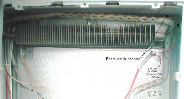
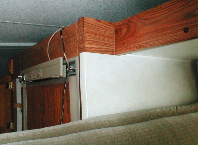
3. Hard to see but after roughing in wire I used some closed cell foam, sold as caulk backing, around perimeter of fridge to seal. I had noticed this gap, could see daylight inside when I had done insulation work some time ago. Cool no more outside air. I'm also going to do a bit of caulking in the box. This was needed with or without fan install.
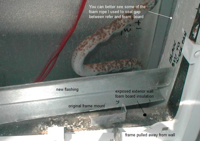
4. In deciding how I might attach deflector at wall, verifying angle enough so vent door doesn't hit I started seriously looking at how vent frame was attached. As it was loose figured I should recaulk. Hole was is cut in wall, so the sandwich of filon,foam,inner ply exposed. The vent frame really only covers half of foam core. No frame like cabinet door, some black sealant was applied to foam insulation. Metal clips were shoved into foam insulation & the frame screws to them. Nothing stops water from penetrating. .Just a really really bad installation.
I decide to pull vent frame and slip a piece of flashing underneath.This would seal the opening and stop water , also give me something to attach deflector sheet to. This side tracked me quite awhile. Liberally caulked opening, placed flashing reinstalled vent frame with 3" screws into foam, use original angle clips attached to walls to back support top flashing leg.
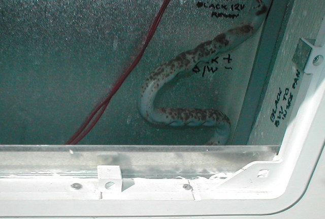
5. Vent frame reinstalled, caulked a line where frame stops, only covered about 3/4 width of wall foam. Slid it back on so caulk underneath. When set I'll caulk the flashing again so flush to top of frame and water will not pool against flashing. Worked well, pulled frame back tight to wall, wont leak but wasn't part of the plan.
6a. Fans arrived, cool. I'm building a frame out of 3/4" al angle for fans to set on, was waiting to insure fit. Measuring 15 times trying to get elevation and checking depth for fans, angle & height of 6" aluminum flashing I'm using for deflector was painful. Got some close numbers then it was cut fit recut fit bend fit drill for about 2 hours. But got it done. End pieces are folded, making an ell, attached to inner side walls and rest against back of outside wall. Using fan to set cross bar depth scribe end pieces, drill hole in end pieces and slotted cross bar for some minor depth adjustment.
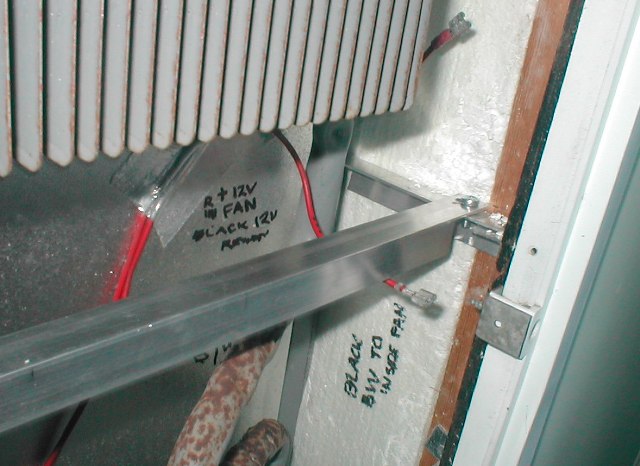
6b. To this frame I'll attach new deflector and at wall. Fans will sit on top of cross bar, screwed at outer corners. Inside edge of fans will simply set against refer wall. I'm attaching foam tape to wall, cover with foil tape to help support but mostly to dampen any vibration. Other than that fans will be hanging. Once cross bar drilled for fans Ill shape angle edge where fans sit so no protrusion into air path. Fans will be centered bout 1 1/2" apart.
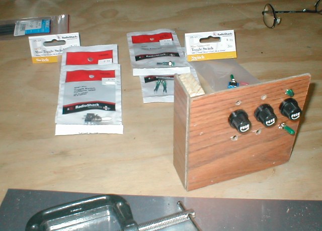
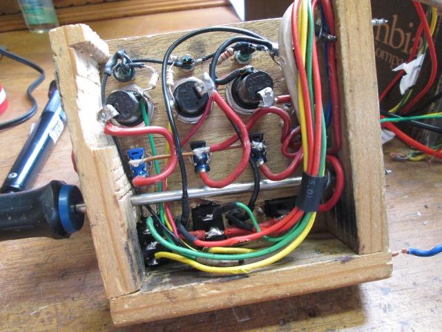
7. Had started a small box that will house switches and fuses. Stopped to build fan mount install & wire fans. I'll pre wire as an assembly with a short pigtail. Once mounted connect switch leads to wires I roughed in. If I determine the location I could finish switch wiring...but stopped to focus an fan installation, but mostly cause I'm still not sure where I'm mounting, that and pilot light issue. The pilot lights I bought are like lasers...really tiny but super bright need about a 1/4 strength. Hopefully as I bought these i can just dim them somehow? That and its looking like something I bought 1965 to add reverb to my blue light 8 track...
8. Finished installing fans on new mount. Finished wiring at back of refer. Had to rethink my original wiring plan and how to use the already pre run wires as I had already sealed up back up refer. Was going to use 12v power and ground from front of refer that I had added for another project (not part of refer). Had Pre run 2 wires for to/from new thermo and 4 wire cable for fan power & ground.Simple. But realized when I started to wire fans that this would not be part of refer safety cut off circuit. Our fridge power goes thru thermal fuse and disk before entering control board. If very temps are reached (fire) this shuts off refer. Don't think I want fans on if this happens. errr. Well if not for safety circuit org plan would have been a cleaner install. This rethink took most of the day but ended up what most would do if switches inside?.. see diagram.
So the 2 wires I was going to use to /from new thermo disk are now power in constant & from new disk. Ran a fused power wire from after safety thermal connection at board and spliced to pre run wires. I also was going to ground at front of refer but just ran a ground from refer terminal and spliced to fan grounds & the extra wire that was in cable now supplies a ground for interior pilot lights instead of carrying ground from fans. The diagram probably explains it better (see below).
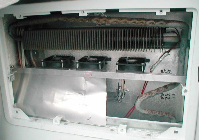
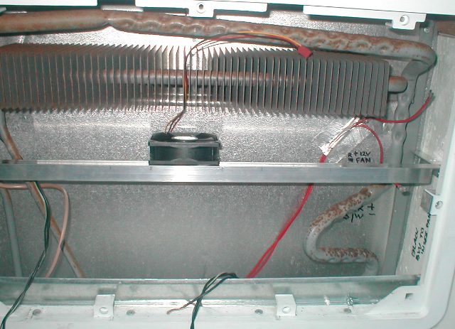
9. Used foil tape to secure wiring to back of fridge-worked well. All connections are soldered & heat shrinked. Had really considered a small terminal block for all connections-but its a fridge. If easy way to attach to back of fridge I would have, maybe, even a terminal block with fuses. Though nice, easier to just hard wire. If fans need replacing Ill cut at fan. Fairly happy with the install. Just took way too long. Tied raw wires inside together to test fans, wanted to see draw on lower vent. Zip nada, then figured because I haven't made deflector yet fans were just pulling air from top vent, place a couple of magazines against mount. Cool fans drawing air in from lower vent!.
Had scrap of the flashing I'm using for deflector. Very stoked, its going to pretty much be snap in, it will be kinda S shaped nice. When I built mount I added (not shown) four 1" pieces of angle inside to stiffen angle. The flashing slips in between, the bottom in between vent frame clips, pretty tight against added rain flashing-. I will make deflector 2 pieces so I can cut to opening profile and reach .
10. Deflector finished & installed.
Well that was easy. Kinda had an idea this was going to be fairly straight forward the closer I got. But not by design, cause I only had a general idea of what I was going to do. Stuff just started falling into place on its own. I had some 6" aluminum flashing thought might work. When I fixed the vent frame and added the flashing at bottom to keep water out, I inadvertently gave my self a place to attach bottom of deflector. It also gave me more height with the 6" aluminum sheet I had. When I added the stiffeners to the fan mount angle I also inadvertently created a slot that top of deflector could slip into. Realizing all this when I used the scrap to cut match the side profile just was well I couldn't believe it was going to be that easy. I must not be allowing for something.
So I spent a lot of time going over what I was going to do, trying to see the flaw. I had to make deflector 2 pieces to get past the smaller hole than inside dimensions. But I cut the short side, slipped it in,. . Cut the long side. Slipped it in. both pieces set about 1/4 of the bottom but began to think there not going to want to stay, if they slipped down wind thru vent might pop top loose even though it couldn't go anywhere it might get noisy. THen I saw the now unused vent frame clamps. If I put a machine screw thru them with a nut on other side when screw tightened it will clamp the deflector to flashing. Unbelievable. Grabbing 2 screws and nuts the length was perfect. Just plain luck. So the fans are mounted wired and deflector installed. Now that deflectors in, I can really see that is going to help, as the rising air will actually pass thru fins instead of just spilling out vent.
I decided to reinstall the 158 thermo disk on factory fan, I don't really want it going on. With the high temp disk it probably never will with the new fans working. It will serve as a back up. On to finishing pre wiring my switch box, install it and finish inside wiring
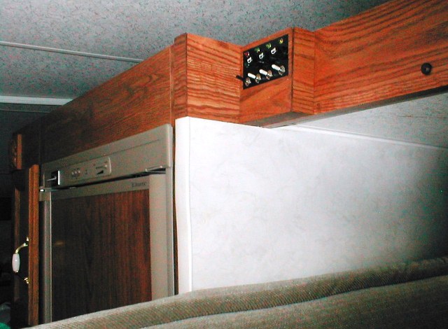
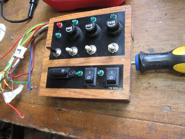
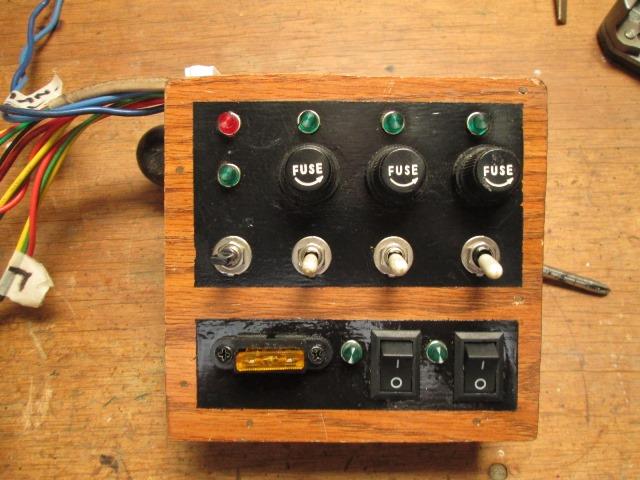
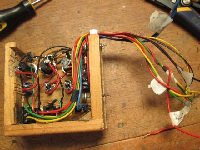
11. Finished pre wiring of switch box.
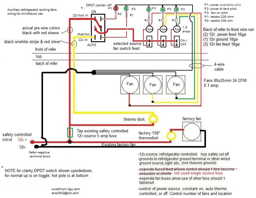
How I finally wired. Looks complicated but not, mapping makes it look so. If you use 12v source after thermal circuit but before it goes into control board should be good to go. What I didn't want to was to put any extra draw on or thru board. If you need to go thru circuit board, have large draw fans, Id use refer to signal a relay and use power from main feed terminal (see suggestions page). What would be considered a large draw?