Install seat heating pads in our 01 Ford Super duty F 250
 IN PROGRESS...
Been on the wish list for ever. Seat covers for our truck.
However this page really about pre installing and wiring seat heater pads that we're adding before covers arrive. Documenting mostly to record wiring for seater heat pads. Which went thru several wiring changes.. ended up installing PWM switches to have fully adjustable heat settings.
Picture generic from order page colors were getting.
>
- Split into sections, This page done while doing the install-mostly for my own reference-really messy.
- Thinking out loud, plotting planning justification Intro this section
- Installing Passenger seat heater Installed then rewire so both seat will get power thru IGN relay that can manually be turned off. Each seat has own power switch. Then rewire to use PWM controller for variable heat
- Installing Driver seat heater With PWM controller
New seat covers on order-5 weeks out. With time decided to add heating pads to passenger seat. I may add to drivers side if install goes well .
Installing seat heaters

Heater kit: Dorman (WaterCarbon) X18203 universal heater kit. Complete kit includes pads, harness and mics to install under factory covers. As we are installing new seat slip over covers simply installing on top of existing covers so do not need to remove originals.
Also not installing these for warmth but for heat/comfort on long road trips so I'm going to 'stack' both pads on seat back. Attention needs to be paid on wiring, where and how its going to be routed BEFORE attaching pads.
Passenger seat:
This went thru several wiring changes. Installed as supplied, then spliced in PWM controller, then rewired eliminating supplied switching relay and unused redundant wiring from supplied harness.

Pads attached. I played with these quite a while trying to get cords to be unobtrusive. Ideally cords would be on left side but short of cutting holes in seats and running inside of foam just no way to get down. I want easy future access, to be able to easily get to pads, replace if needed without seat disassembly.
The pad cords exit out side, to get orientation and cords to lay flat as I wanted and cables means they will run down right side of seat. To get pad plugs ending up at same location/length under seat due to being stacked I did cut off both pads plug. With 2" of wire on one pad and 8" on the other then swapped and soldered. Pads have self adhesive tape that adheres but I also stitched top corners to seat. Cables sort of tuck in seam between back and side bolster so should't be felt.
As passenger seat wiring ended up at far right of cab getting to dash cords will be too short by about 2'. Splicing in some wire needed. If when I do the driver seat cords would be in center of cab so length should be ok.
Just showing cords running down. Exit facing back of seat bottom then between seat bottom and plastic trim.

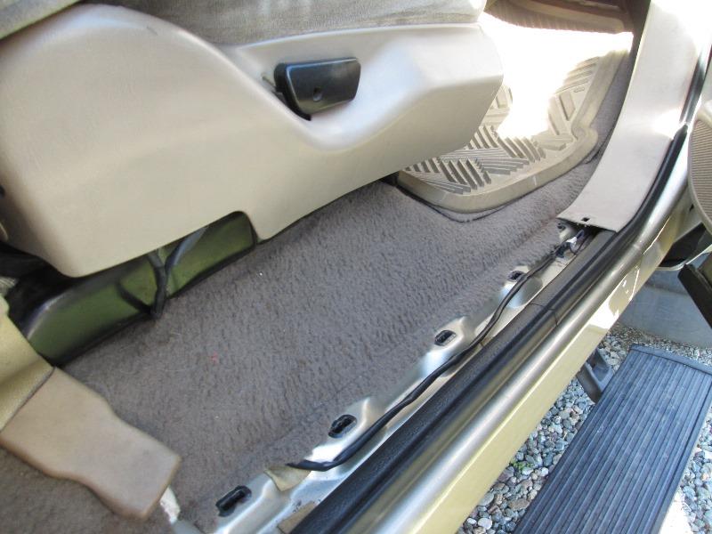
Cords plugged in behind seat plastic, go under carpet into door sill and run up into kick panel. Where cords start up into kick panel is where I cut (3 wires) and added 2' of length.
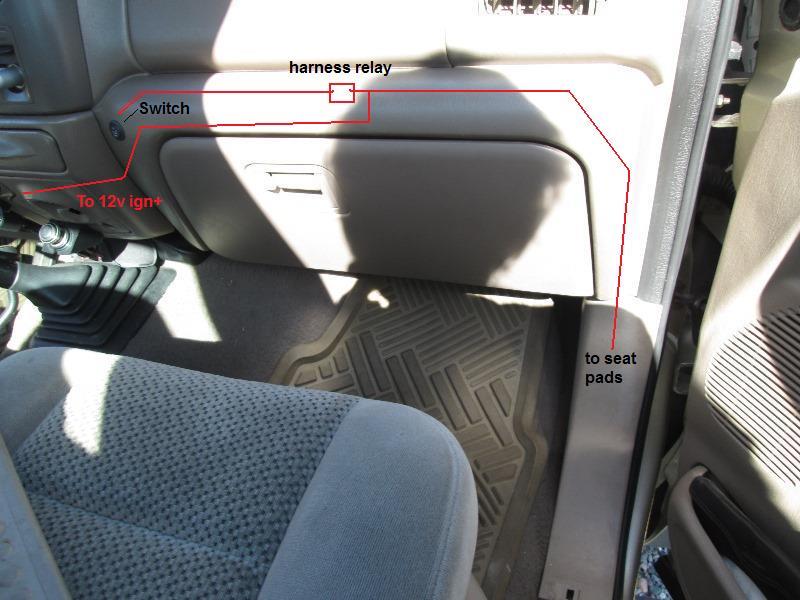
Cords run up over glove box to installed hi/off/lo power switch. The harness plugs and relay are above glove box door and can be accessed.
FYI

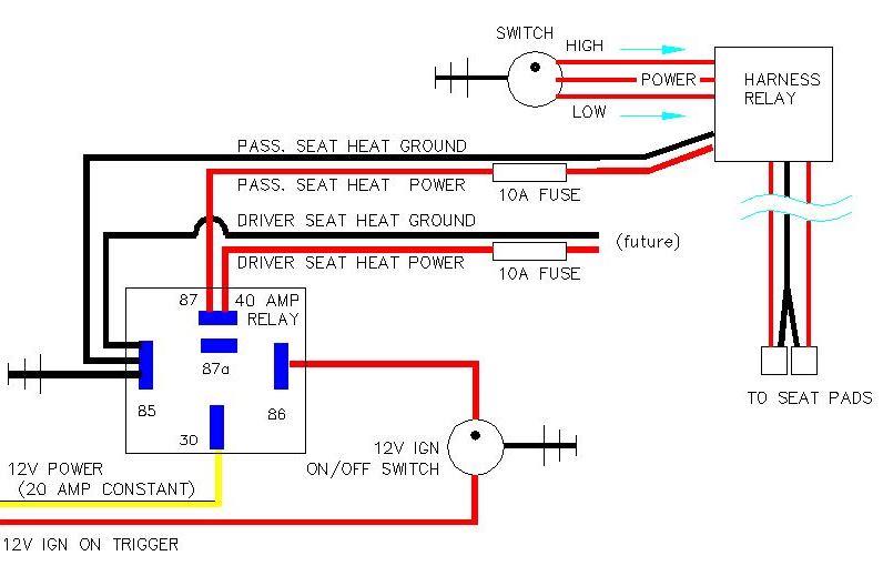
The included harness is bit odd. Main included relay that switches hi/lo power feeds cable that runs to heat pads, cable that runs to switch pigtail, and power/ground lead that runs to power source. Hi/low setting is accomplished by relay switching, either by sending 12v to each pad or 12v to one pad that then continues to other pad. Uses resistance of power going THRU both pads for low setting. The Hi/lo switch basically only turns on/off the relay. Consumption= Low is about 1.5 amps, high is 4.5 amps.
Intended is the power input is attached to ignition on power, tapping at fuse block with include fuse tap. However on our truck would be another 2' to reach fuse block. Under steering column I have an existing 20amp unused power feed. Though its hot all the time.
So I am adding another relay using existing 20 amp circuit that will be switched by tapping ignition trigger wire for air compressor relay. Im also putting interrupt switch on trigger wire to disable so heater relay isn't energized with ignition 90% of time seat heaters aren't used.
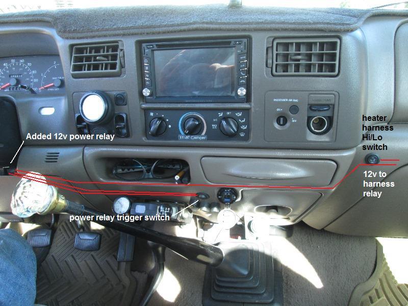
Really nice is when/if I do the drivers seat I can plug its power feed into this relay with no additional wiring.
Cool! heated seat.
Rewired splicing in a PWM controller for variable heat control

The only thing to pursue as far as heater is some how adding a medium heat level as I gather the lo is barley warm and hi is too hot to leave on. Thinking on the hi setting is adding by pass so either full power thru or thru something to regulate voltage. Wonder if you could use simple variable PWM motor switch on electric heat pad? Problem is heater high uses individual wires to pads, might be single exiting relay....hmm.
Looking at included wiring diagram just doesn't compute...DOH!!! starring at it realized Diagram is of switch in off OR high position as really 30 is connected to 87a, weird.
Relay not energized (hi position) power goes directly to pads then ground of one pad is direct the other goes thru pin 30 to 87a then to ground. So on high both pads are receiving full voltage from switch.
On lo setting power goes to 86 AND 87, energizing coil connecting 30 to 87 so power flows thru 87 to 30 to one pad then goes thru second pad to get to ground ODD
Bottom line output from switch hi terminal is direct voltage that regulation would turn down heat of both pads. Still dont know if PWM would work as they usually want to control ground also TBD.
I've ordered heater for drivers seat and two 15amp PWM switches. I'll play with drivers heater and test its relay and switch and test PWM before installing to see if easily modified.
It works!
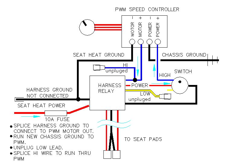
On the bench, spliced in PWM on high output wire from Hi/Lo switch running thru PWM. Works great. Problem is after doing realized 2/3 of existing heater wiring could be eliminated. Lo position unneeded so the relay could be eliminated also the hi/lo switch. Way simpler-. On the passenger side since wires already run will splice in PWM as shown. Secondly if issue with PWM can be easily reverted to factory hi/lo by unplugging hi lead to PWM, plugging the hi wire from relay back into hi/lo switch and chassis ground the seat ground wire.
Passenger seat pads installed and working with variable heat control.
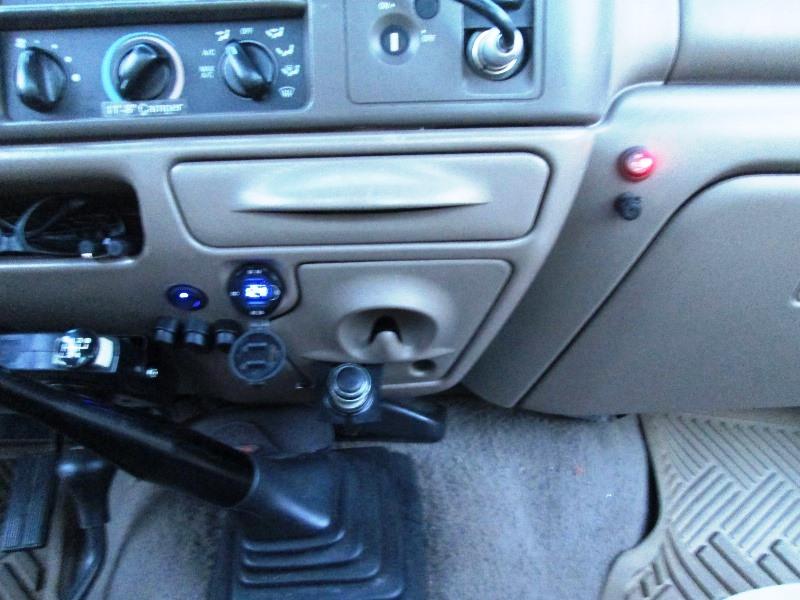
Nice. Bit of effort. Drilled hole below switch for the PWM adjustment knob.
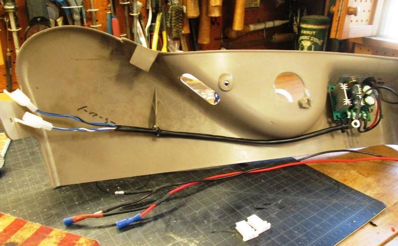
Only place to mount PWM board was above & to left of glove box lid. Used plastic serrated body push clips on the boards 4 corners to act as stand offs.
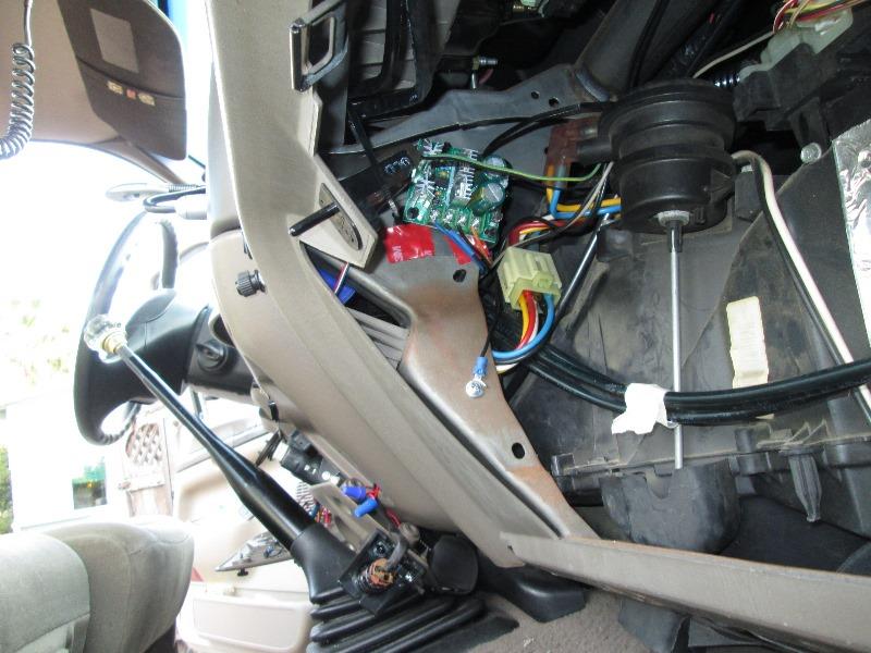
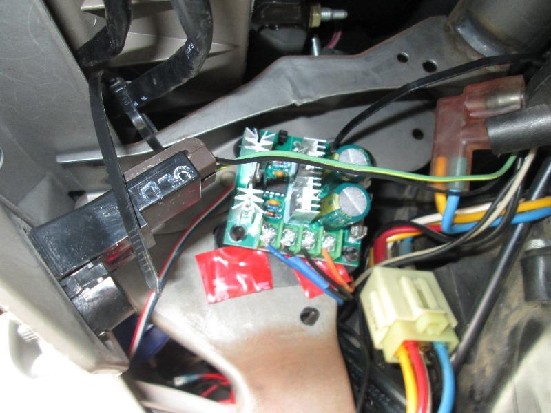 Hung with zip ties and 3m tape under standoffs. Wiring was a pain but its done. This picture is causing me to drop glove box again as the light wire looks really close though pretty sure its like 2" further and cant touch heat sinks but need to look...
I did unplug the yellow LO wire from switch so it cant turn on . The PWM on a lower setting also decreases the power energizing the coil causing it to chatter plus the lo setting not needed now with the PWM controller.
3rd rewire... removing harness relay and wires

Wires & relay removed. On passenger side I removed the relay but kept the 4 pin harness plug as 12v power already routed. Removed all the yellow wires. 12v power goes thru this plug and back to switch then to PWM. (supplied Chassis ground wire NOT connected/not used) Noted but again the blue power wire feeds both pads, its the grounds that are separated in supplied harness. White to one pad, black to the other. The white and black wires to pads are tied together using PWM 12v- out. The 12v+ out from PWM goes to blue. So both pads receive hot and ground from PWM.
COLORS are not true.

Power runs thru plug directly to switch, from switch to PWM controller. Output from PWM runs to seat pads-similar to drivers side except switch and controller are on dash. Not quite as clean as drivers side but better than it was. I grounded the switch pilot to PWM out ground, lets the LED act as visual. I may move the drivers side
The yet to be installed drivers side Im going to rewire completely replacing all of the included harness.
This is how I should have wired from the get-go. Eliminating the bizarre (though functional) wiring harness, relay and 2/3 of the wiring. Im sure this shouldn't work and good reasons not to do but on bench had running for an hour, turning on/off and back on few times, adjusting temp and no issues. Time will tell. I am going to create my own replacement harness so that IF long term issues I can install factory harness.
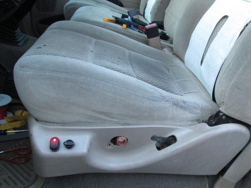
Looking I could not find room anywhere to mount the drivers side PWM behind dash. Then I looked at maybe hiding under seat and....

Already removed but on the side of seat trim is a bump out that would be perfect to mount switches. Thinking this may be used on trucks that have power seats. Easily seen and used---dang it. Dang it cause I didn't see this when doing passenger side. Though when started wasn't using PWM and I wanted easy access to switch, however placing on seat wouldn't have 2 holes in my dash... I will be going back on passenger side switches-try to come up with a trim panel for the 2 switches so it doesn't look so hokey.
So plan completely changed again. Mounting PWM controller and switch on side of seat trim. Only need to run power wire from dash power relay., ground to seat base. Orientate the pads so wires come down left side and plug in under same plastic trim.
FYI removing trim piece- removing the lumbar knob is a major pain, you simply pull REALLY HARD and then pull harder it just snaps on/off the shaft. Actually got on line to see how this was supposed to come off cause I though I was going to break it.
Also the front I thought I needed to pull the 2 plastic rivets but underneath are 2 screws attaching arm that rivets go thru to seat base. The rear back of trim is a large push pin which did break, and 2 screws, one under the tilt lever remove 1st before removing lever.
Ok enough o f the FYI as I really doubt anyone would be duplicating this or at least here to find info...
Got the side panel pre wired.
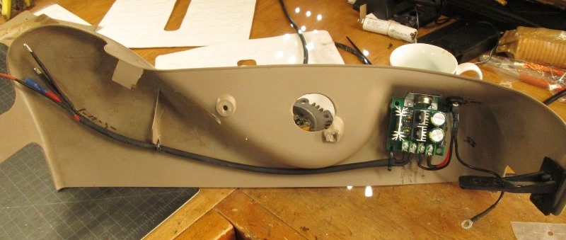
Power from dash (plugged into added passenger relay) runs down kick panel along sill then up behind trim and onto simple on off w/pilot. Ground will be to seat base. Wires from PWM terminate in Y with bullet connectors to feed both pads. To the pads I spliced in corresponding bullet connectors. I left factory seat plugs so I could install supplied harness but dont see that happening.
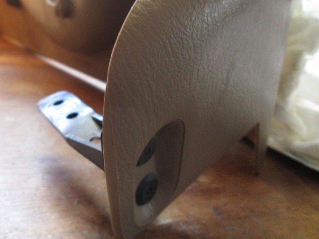
Pads installed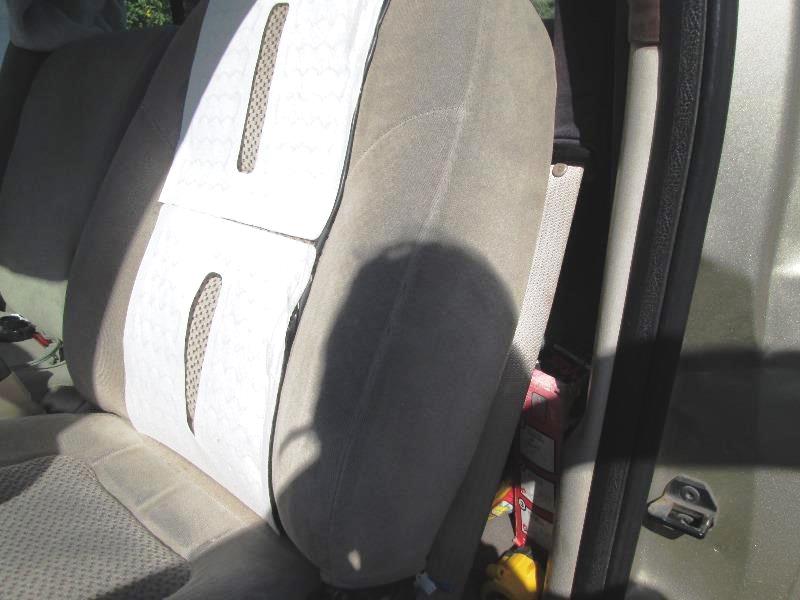
Pad wires I had extended both leads but still ended up a bit short of plugging in behind set trim loosely. Not sure where I erred but I did. Oh... it was rotating pads on the fly so wires come down left side of seat instead of right side like passenger seat, dumb ass. Leads exit top of pads instead of bottom-about 8" difference. I was going to route same as passenger seat down right side, run leads from PWM across back to plug in but decided to come down left side to plug in on left side. Didn't take into account rotating pads ate wire length.
It works but when seat folded over to access behind plugs can be seen, not sure if new covers will work with this. Need to seriously look see if I can reroute so plugs end up behind plastic trim. ...But I'm pretty sure need to bite the bullet and redo wiring and extend leads several inches. And writing this determined that's what Im doing. Remove added bullet connectors. Cannibalize harness that came with kit (which I should have done in the 1st place) for the sheath and its plugs add to PWM leads, extend seat leads maybe another 10" utilizing supplied plugs. Minor if not having to do with set pads already installed.
Not sure why but EVERY time I adjust plan mid stream it often bites me because there was a reason for original plan.
Temporarily sat the trim in place plugged everything in. Had an old knob so I can 'feel' its rotation. Straight out as shown is about half power to pads. Tested and it works. Started truck and enjoyed the heat for a bit. NICE. Tomorrow rewire plugs. Minor if not for having to solder on seat :(.
Removed previous wiring/bullet connectors from PWM to seat plugs. Cut off leads from harness relay to seat pad plugs, wire to PWM using kits harness plugs.
Extending leads for pads. Cut the harness grabbing some of its wire and sheathing and spliced between seat pad plugs and about mid of lead exiting pads, extending about 12". I did remove pins from plugs to slip heat shrink and sheathing over wire.
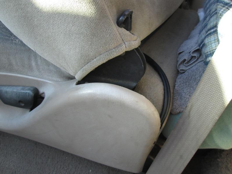
WIre relaxed, easily reaches behind trim. Before plugs were on top of seat. Can be moved if needed once seat covers arrive. To do is stitch a loop to ensure wires can't migrate toward the hinge, though covers may remedy that, wait and see . Slick, I like it- 3rd times a charm. Trying REAL HARD not to duplicate to the passenger side. Only reason I'm not is the stupid holes drilled into dash.
Throw towels on seats to protect pads until covers installed.
Waiting on seat covers to arrive. Likely will only add pictures of finished install.
Seat covers arrived!
Back to our F250 truck page
Back to Ourelkhorn Camper Modifications page