Add Split 110v receptacle to other side of table
-
Originally on Table shelf mod page I move this addition here to its own page. Just A Continuance, or actually part 2, of modifying our campers dinette table. In an effort to 'clear' the table added under table shelf, which can be seen Under table shelf page. Which led to this project, seemed simple enough, extend/add second split 110v receptacle on other side of dinette. Just ease of access to power when we have it or inverter use, further effort to keep cords etc off table. Also add remote inverter switch. Initially after getting to use our "new" table this was one of the small details, adding second plug. We will be adding USB ports but this just made sense to me and buttoned up before that occurs. However the plan change before it got started, primarily how I added new receptacle. Spent more time on this silly plug than building the tables shelf.
- Add 110V receptacle.
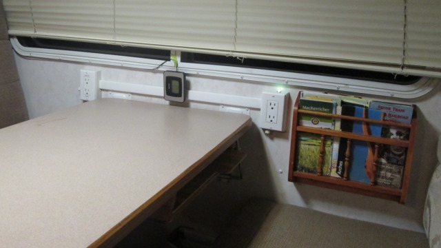
Extended previously added split inverter/shore receptacle to other side of table but went over top of table. This will be convenient-keep cords off table, access inverter or shore 110v, decision was made to go over top-just easier but really don't like it. That and the whole time I was thinking I should be adding USB receptacles. But sometimes we have shore power or the inverter is running or the generator is. All about options and convenience, this is addressing the 110V.
Was happy with the vertical wiremold up to plug from previous install, should have bought more romex to run under floor and up to other side to match. Laying out and evious install, should have bought more romex to run under floor and up to other side to match. Laying out and preliminarily looking it seemed it would look ok to run across table. Justify & let me use material on hand, simplicity of just tapping and running across table which was the real clincher. Oh well-maybe it grow on us. I should note the source for shore 110v is from GFI plug on seat box so these, on shore, are also GFI protected.
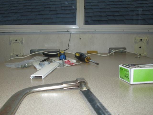
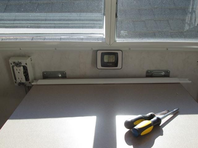
First is too get the wiremold box base installed, then the wire cover base. Pulled of magazine rack and thermometer. I was going to use the table bracket screws to hold cover channel, would kinda hide brackets, be closer to table so visually less noticeable and allow our thermometer to remain. However discovered the distance from table to window is not the same across. Never noticed before but window is almost 1/2" higher toward front of camper. Also the table bracket on right sets about 1/4" higher from table. Fortunately I hadn't broke out the sides of wiremold boxes to insert the channel, it would have ended up really skewed in relation to table. What I did was split the difference in placing the cover. Required raising above brackets with 1/8" above left bracket. Lower the right receptacle base about 1/8". Marked the boxes where wire cover will enter
Crooked as all heck but unless you look at where channel; enters the boxes "appears" level. Pretty funny, I'm use to this in our 200 year old house, where nothing is square or level to anything else.
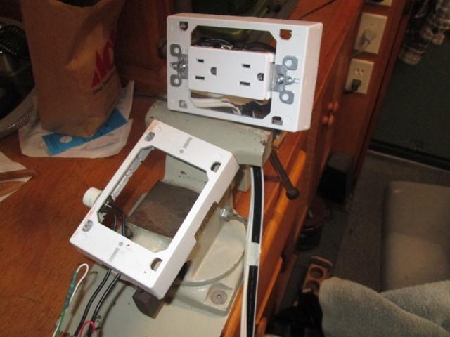
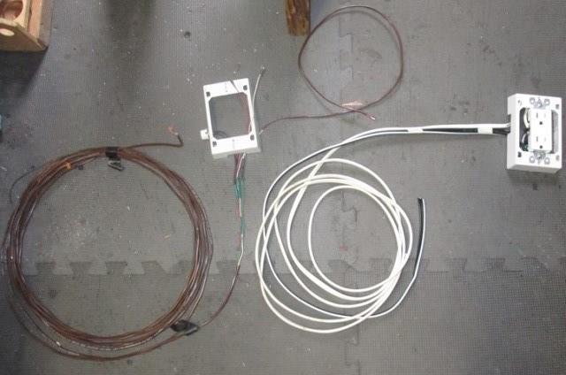
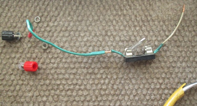
Decided to pre wire additional right receptacle in shop, and add remote inverter switch and wire to left box. Basically this is a convoluted extension cord from inverter. Once pre wired I can just reinstall the left box and wires to inverter can be run later, install the right box and connect its wires to left box. Routing the remote wire to inverter will be separate and last. Used 16ga ribbon CPU power leads to feed new box tinning ends. Used 25' of 18-3 wire for inverter switch lead thinking I might use 3-way switch but used simple rotary lamp 2-way switch due to small internal protrusion.
Then decided since I had an extra lead could use to run ground, just in case I decide I want a pilot lamp. Not needed and probably wont but since I'm here.... So to the white wire returning to inverter to turn on I added a length of red to feed pilot when energized. To the unused green wire I added a length of white for ground.
(I should note: mixing different voltage (12v/110v) circuits in same box I believe isn't 'legal' or recommended. If any consolation to electricians who are cringing the remote inverter switch power & return wires are fused at 5amps. They are completely separate and only lead back to inverter switch, though just realized I do have a path via the added pilot 'ground' wire. If there was a short between the 110v and pilot 12v ground, 110v 'could' travel to inverter battery ground lug- have to go thru 1/2 watt-200 ohm resistor then thru watt meter to batteries. As highly unlikely as it may be, still since this only grounds pilot lamps Ill add a 1 amp fuse, addressed at end. Good catch. :) )
No more than finished, as this is all about convenience, decided to run inverter switch lead to other box and add another switch so from either side of the table inverter could be turned on. Cut 3' from end of wire and ran to other box. Also did the allowance for pilot light. Now I'm wishing I'd used 3-way, as I'm using 2 way switches, which ever switch is used to turn on must be used to turn off. I'll need to modify switches so you can visually see which one is in the on position. Switches are 90° turn, simple ball bit on dremel, dab of paint 180° apart on knobs.
Drilled the bottom of right box for switch hole then went to hardware for another switch.
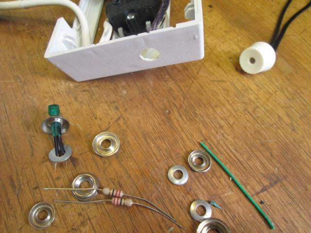
Upon returning realized I had put the hole in top of box instead of bottom. Errr. I double checked but not enough room for switch on top under window frame. Short of buying another box guess I get 'cooling' vent. Making a pilot light to fill hole....I had some that would fill hole but body too large. Used smaller one with screw bezel to cover hole, also adding some resistors to dim bright pilot. All the resisters I had were to large or small so for now running 2 in series. As a matter of expedience added in line on the ground wire. Later (soon, once this is done) Ill remove and add correct size at the ground source, still too bright but mostly to get resistors out in the open.
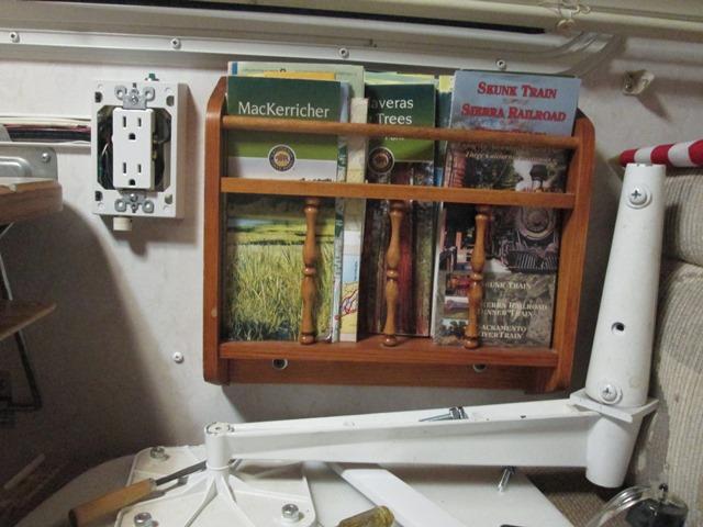
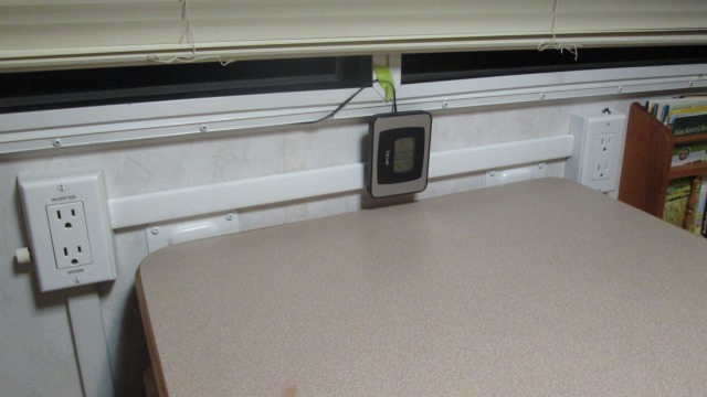
And the right plug installed, reinstall rack. Painted screw in exposed wall hole.
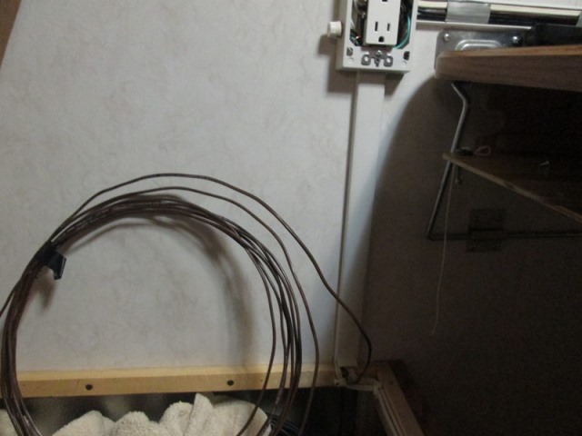
And left side reinstalled. Now the fun part, running 22' length of wire to inverter...Actually wasn't too bad. Though had to pull full length, after cutting total length ended up about 12'. Wiring to inverter, other than access, easy. As I already have remote switch connection for TV just tied into that. The pilot light ground ran to existing remote pilot ground (that's connected to inverter battery ground). This, though lamps use in milliamps, allows to show on watt meter that records inverter use. When I add/change resistor to dim dinette pilot it will be at that connection so all will dim.
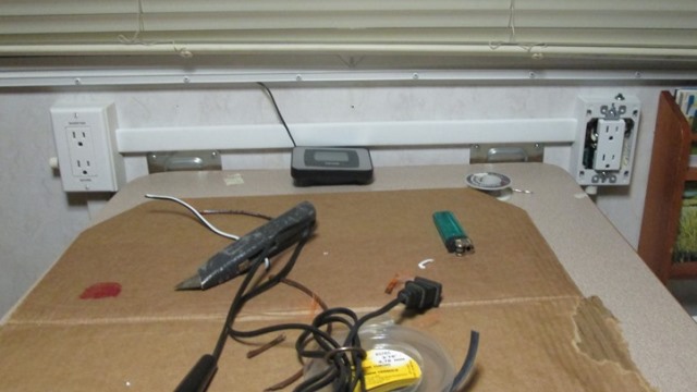
Placing covers on is when I decides I really didn't like the wiremold across the top. Its done though, Margaret says it looks fine....
I pulled the table out and painted the wall brackets. They always bugged me anyway. Helped a little bit. Really to pull the resistors that aren't doing much. Add the fuse and 220 ohm resistor at the source.
Fused ground lead with 220 Ohm resister to soften the led pilot lamps. This will go to battery ground terminal on inverter. And it was going so well...
Working thru 3x8 drawer hole to access inverter wish I could say was fun. Tomorrow Ill go back in and re loom/tidy the wires, I ended up pulling everything loose to access the back side of inverter & made a mess installing the ground fuse, but its done. Opened up wiremold cover and cut out the previously added inline resisters at the receptacle.
But we have easy access to power from either side of table. Just need to place thermometer that's hanging.. Holding off permanent fix until USB receptacles installed. May go in center...to be done. That will be part 3.... I see it as possibly being a bit more than an addition as I'd like to tap unused "clean" low power fuse in inverter. Put the USB ports on separate circuit. Then again...ease of install, may just grab power from Refer supply -its right there....In any case it will be a straight forward 'fresh' install & won't be a convoluted mess as this was. I've come to the conclusion you can only modify the same thing over & over so many times before it really needs to be done from scratch.
Back to top of page
Back to part 1 adding the under table shelf
On to part 3: adding USB ports and 12v circuit to supply them
On to part 4: adding AC/DC laptop charger
Back to Ourelkhorn Camper Modifications page