Flip Winegard antenna head for clearance
The camper gets a new replacement A/C. ....
AS typical.. one thing leads to another..another convoluted messy page..This page originally was on our reinstall page for the AC. Move to its own page because there are folks for whatever reason need or would like to flip the antenna head for more clearance. Adding a wingman feature etc. It is doable.
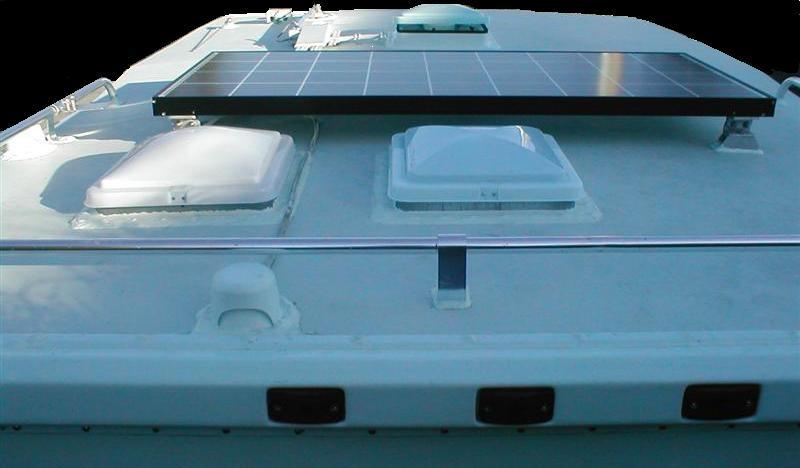
Shown above is factory antenna with wingman feature. Its in the area our new AC will be.
The decision
-
Width wise with new AC the antenna is an issue. It was replaced with wingman feature, seen in the picture above its really close to the vent. Possibly could remove just the wingman feature but the head would still be awfully close, if it cleared. That and antenna really works well.
I'm flipping the head on our antenna 180°. Well the antenna appears everything that could be done to keep a person from rotating the head was intentionally done. Bizarre. Some folks get need clearance by simply shortening the lift arms a bit.
Rotating or flipping the Antenna head
For me hardest was separating the head. Just getting the head apart is a challenge without breaking. In THEORY the top slides toward the big end after releasing or prying a bit the side front tabs, good luck with that. Starting in the middle I pried open until the tabs popped out. Once you get apart its pretty obvious.
It isn't possible to simply to rotate the head so it sets on opposite side of arms. Requires some physical rework and wiring. Became a project in itself, subsequently moved to its own page for what might be gleaned if you need to do.
Ill add a link at bottom to another flip project. Mine was finished a few months ago. Today, rewriting this page, I stumbled on a page where fella did this almost 4 years ago..wish I had seen when I did this-it is almost identical to what I did, looks like we took same pictures, funny. So I'm not the first.
The Plan
This tells all. The internals because all the holes are offset wont allow simply rotating 180°. Reinstalling the arms to swing opposite is only thing I can see.
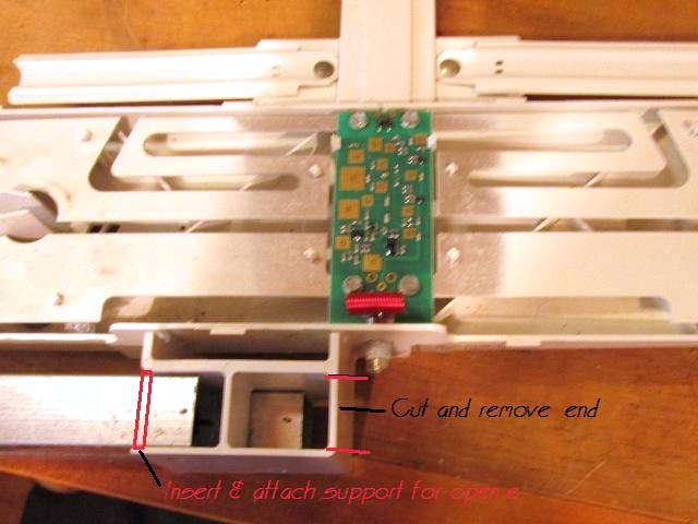
Requires cutting out closed end for arms to exit other end, match drilling pin holes in mirror image. Adding support to close opposite end. Hole placement is critical for arm movement but cutting the end for arms only leaves center plastic web for support, so adding back an end support tying outer plastic wall to inner is the only way this will work for support. Basically just swapping ends, closing open end and opening closed end. New holes should be drilled before cutting web, and stabilize the open end.
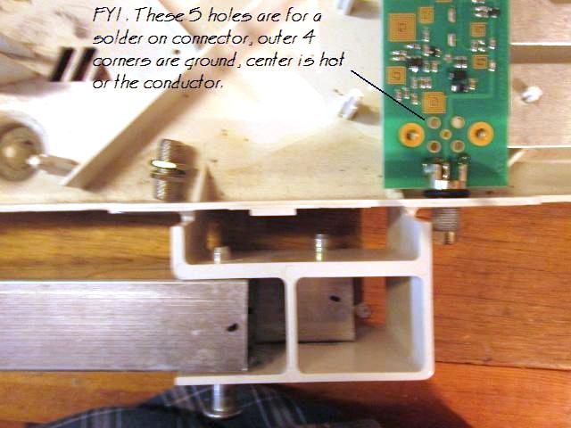
Fine- but the RG59 cable connector is in the way. So I'm adding another connector on opposite side, run a short piece of cable and solder either to existing connector or to the board. There's is another allowance on board for another connector that I could solder to-
At best I'm giving myself a 50/50 chance I can execute this without something breaking- simply doesn't work, board fails or added cable cause signal loss...
And the calm before the storm..
The Execution
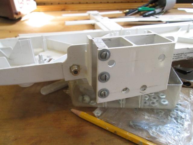
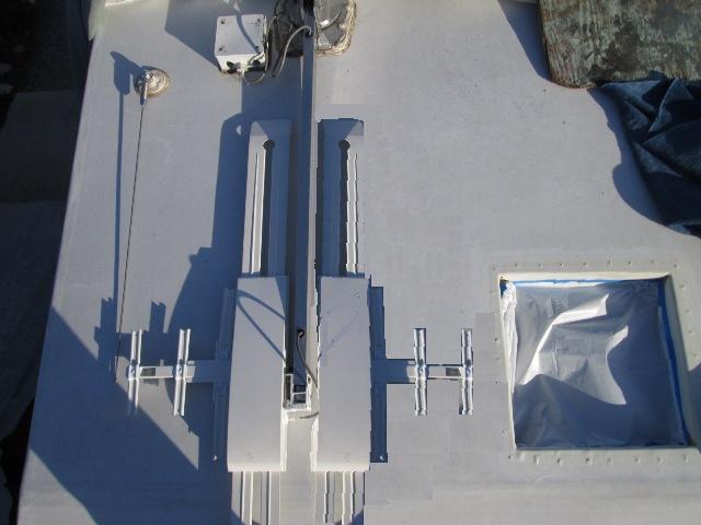
Drilled new pivot holes mirroring existing ones for arms. Cut a 5/16 piece of aluminum, drilled (3) 9/64" holes thru it pretty close to edge to ensure arms doesn't hit it as they rotate. Used 6-32 screws & nuts. Drilled and mounted the RG59 connector.
(*As alternate to plate see link below. He used a bolt in old pivot hole).
Getting ready to cut out the back end for arms.... & paused. I could up to this point put antenna back to together no harm, once I cut were committed, though I suppose I could move the new al bar over. Just pausing-.
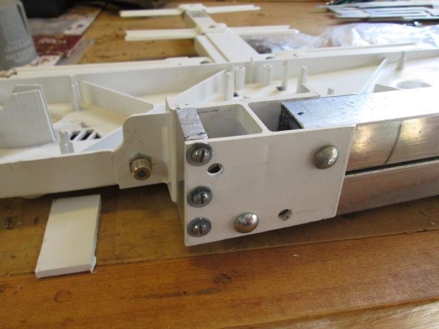
And plastic cut. Arms installed. I was so focused on the thickness of the new al bar and bottom arm clearing didn't note the center plastic web and end of bottom arm.
Because center web its also off center, (and end of bottom arm ends up closer to it) when bottom arm rotates it hits center web. Simple fix-little filing to clear.
Wired. Used a length of CATV cable, has water proof ends. Cut of one end off, shaped to snake under and over to board. Had to dremel couple of slots. Once shaped removed it & board to solder. On the board there is another location to add a solder on female RG59 connector. (http://www.pasternack.com/sma-female-right-angle-connectors-category.aspx) I twisted the outer woven shielding into 2 braids and inserted into ground holes.
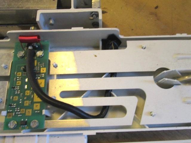
Looking at this picture after reassembling decided to take back apart. The outer shielding really didn't solder well. I have good continuity but I'm taking back apart and add a ground lead from the connector exterior directly to the board, in case the soldered shielding looses contact there will still be a ground path for the power amplifier ground.
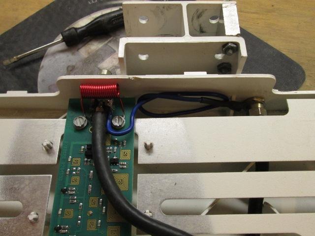
Ok now were happy. Additional ground path, shielding will still work as that if soldered connection dumps at board end but the amplified board wont work.. The top cover does slide back on easy enough. Sealed old connector with shrink tube, if not for the amount of solder holding it to board I would have removed.
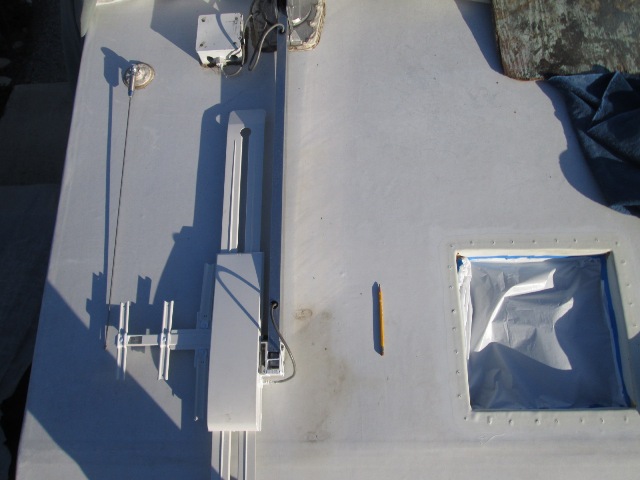
Now to reinstall on camper to see it lift. Hook up the TV and verify I still get signal.... Also looking at the picture I'm questioning the cable running over top of board. Might have run a longer piece of coax and attached coming in from side. Better yet use right angle connector, I 'think' a simple RJ59 right angle connector might clear so wiring wouldn't be necessary and use existing connector, cable would need to be secured to head (zip tie,clamp) so it didn't unscrew itself. Not sure there is only about 5/16" space. Something to try.
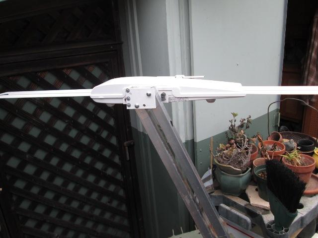
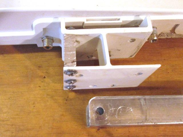
Just showing head on opposite side. I'm unsure why Winegard doesn't make a left or right side antenna. Or better, a simple redesign. If the mounting block on head a little longer, 2 center webs for rigidity, symmetrical with holes for either location, arms would bolt form either side. Simple modification, swapping swing and head. But were done, antenna modified for AC clearance. Wonder if anyone will note our antenna head is backwards?
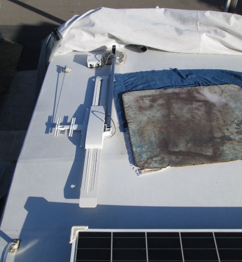
Ran thru TV, raise/ lower head, rotate everything still works.
Only thing on ours I don't like is the wingman so close to edge. I may add a riser (or tennis ball) on radio ant to act as a bit of branch guard. But done so I can continue AC reinstall.
- Options
Similar thread on RV.net about flipping antenna, toward end is where photo album below and identical winegard head flip was linked
Thornoli's Antenna Mod album Only difference I see basically is using bolt to stabilize the open end of plastic verses using a block, might be easier. -better pictures
Back to Ourelkhorn Camper Modifications page