Modify/Fix Cut 50-F Plasma Cutter
Very inexpensive plasma cutter, out of the box it needed some attention. For the price as long as it functions still pretty happy, but for the price one should assume inspection required before use. Mostly for my own documentation of what I and others found- addressed and noted. Since I had case open- many were things I just didn't like or could become problem down the road, IE wires. Some were cosmetic ie rerouting lines. Some were quality control issues, just the way its made to save money. I would rather spend some time now if it 'might' stave off problems later. I did change couple of things, ie replace power cord with longer one etc. In no particular order what I did, what you might look at on similar machine and my 'personal' mods.
Price was the only reason I ended up with plasma cutter. As nice as they are could never justify cost. An opportunity arose I couldn't pass up. But price also means generally get what you pay for. Not like this was 50% off a known national quality unit. Generic off shore clone. Took 4 months to get. This one made in China. I assume similar units might have same issues though quality probably better than this 'special' production group buy unit. Anyway just documenting what I found, changed / fixed. Primarily for my own record.
 Specifications:
CE & CCC approved
Input voltage: AC220 V Ý1 5% Single-phase.
Input frequency: 50-60HZ
Power factor: 0.93
ARC starting way pilot arc/untouched
Cutting amperage: 20-50 A
Max Cutting thickness:20 mm (25/32")
Rated output voltage: 100 V
Duty cycle: 60%
Efficiency: 85%
Weight:9kg (20 pounds)
Dimensions:
385x 155x 295mm
6 16 1/8"x 15 5/32"x 11 5/8"
This page is very long, all plasma cutter mods listed. Required QC fixes and usage/personal preferences changes
Out of the box-this section. Observations, assembly and other mics..
What I found and addressed general
Restrain trigger wires in plug. Ill fitting 2 pin connector doesn't capture wires
Fix torch Rotating switch on handle discovered two serious issues. #1 thing to inspect if you have similar machine.
Customization:
Minor changes Changed the way regulator plumbed, add grommet for gage hose
Power cord Replace 8' of 12ga w/ hardwired 20' of 10awg power cord
Cutting Cut some disks
Ground clamp Inside strap too short. Minor details.
Replace cord again 20' just too short, replaced with 35', hardwire receptacle to make cord detachable.
Add switch to torch switch feed Torch too easily tuned on when not cutting.
Drill couple holes in bottom of case to hold points post if adjustment needed, secure cables.
Starting at the beginning. I was not in the market for a plasma unit. Even cheap ones way out of my allowance. As mentioned I got in on a group buy, price was so low worth the gamble. Worst case in my opinion is it stops working. I honestly wont be too upset. I really would like to see of these units that are sold normal retail, It could very well be, as most of what I found were assembly related shortfalls, that these 'special' production run units were just pushed thru the line. Worth spending sometime time and nut & bolt before use.
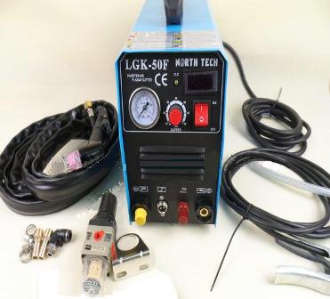
So 4 months of anticipation: it arrived!!

Pretty excited. The fella that coordinated (actually did ALL the work making this group buy happen !Thanks Sean!) had opened up one of the units. Brief inspection he noted some things we might look at. So I planned on going thru it. Also these machines don't come with end on cord so a trip to hardware store in order before use anyway.

First impression I like it. Comes with everything except plug for power cord and air line quick connect. I hadn't pick up plug because I wanted to see supplied cord. I already assumed I if too short to use without extension cord I would swap power cord for a longer one. Well it comes with about 8' cord still too short. So hardwiring a heavier 20' cord and plug to match existing 220v receptacle.
Second was looking at the air connections. I have quick connect and a small inline dryer I'm using for now. It was suggested, as fittings supplied for air line between regulator and case cause it to loop pretty far outside of case that ells might be used. I agreed , would 'tidy' up considerable. So with hardware list ready proceeded to inspect/check machine nuts bolts screws connection etc.
Overall impressed with unit given price. But yes some details need addressing.
First, as I was opening up anyway, was while off prep and repaint the very blue case. Well the better half really liked it so I guess it'll stay blue but I did peel off the stupid people stickers. Stuck on bottom in case I sell.
Found 3 clearance issues on the boards and wiring. Not immediate concern but I saw as eventual problem and fixed. Minor and shown below. One was middle board was flexed downward quite a bit. Small vertical top board was under case brace pushing it down. Circuit boards don't like to bend. One small wire loom was pinched under case cross brace. Again minor and fixed.
Power cord restraining gland was a little loose, though its pretty soft plastic so I wouldn't reef on it. There is a large hole on bottom of case, I looped large zip tie thru and pulled cord tight to bottom further restraining immobilizing.
Small 2 pin trigger plug on front from torch, the wires are unrestrained, likely eventual source of failure. I addressed below. Others have found loose screws, loose standoff on the boards so just look and check everything. Don't reef on em just ensure snug, check all plug in connectors, also checking that the pins don't protrude above plastic housings, I found one pin pushed out of housing.
- Fixing QC issues
#1 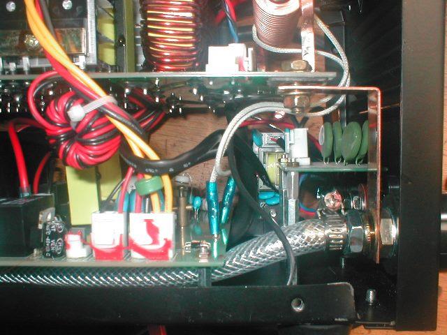
Here I've already loosened the bolt. Board sprung up bout 3/16". Loosened the nut airline goes thru that mounts the bar but L bar would not move up anymore.

I removed the L bar and slotted with file. Maybe as this is a conductor bar if I had some copper washer could have spaced, I wouldn't use steel. I checked other side conductor L bar, it was fine.
#2 
Then I noticed the small vertical circuit board. It was under the chassis cross bar, being pushed over & down quite a bit.
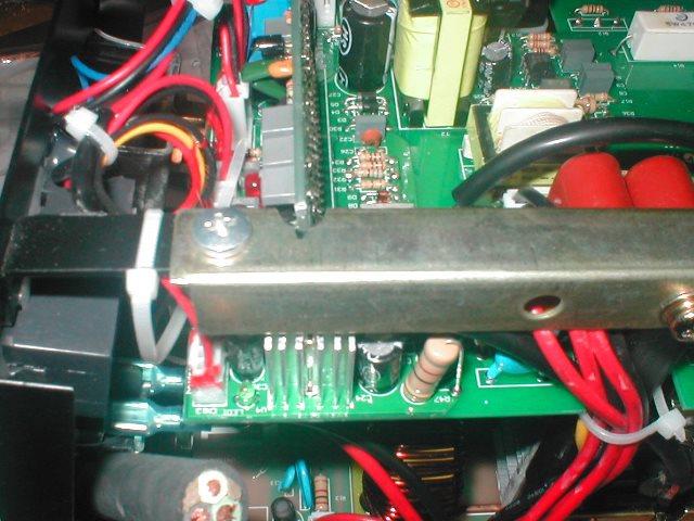
Removed the cross bar and file clearance
Board is now a good 1/16" above bar.
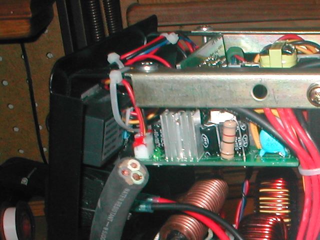
#3 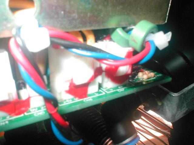
Fuzzy pic but on the opposite side wires from plug pinched under cross bar.

I removed and filed for clearance but the little donuts kept working up either side of bar (with wire back against the bar) so cut zip & reroute wires behind bar. Also it was this plug, probably due to being pinched that one of the pins was not seated in housing.
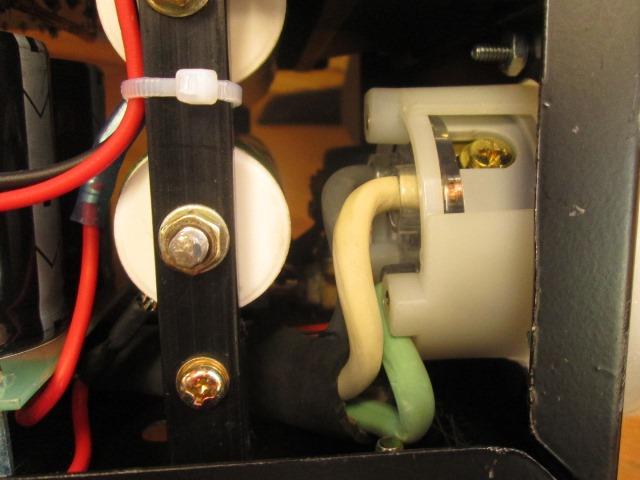
The white tie is getting routed thru air line fitting mount hole. Its to keep the elbow from rotating keeping the plastic air line as far away as I can from the what I assume is hot coil. Update I used cutter a bit-checking with temp gun I didn't see high temps on coil below air gage fitting.
Those were the only internal QC issues I found, no loose screws, nuts etc.

Other than the top board front 3" just hanging out, no support. Not an issue, could be but I didn't like. Made a small bracket, screwed a small block of PTF to it. Drill hole and mounted using gage mount screw with a nut. Applied some thread lock on both gage screw nuts. The board just rests on it.
- Couple simple changes I made.

Unit comes with straight barb fittings, simply changed to 90¯ ells so hose goes straight down. Mostly an appearance thing, will store more easily You easily could use 90¯ ell on regulator, leave the straight on lower or barb/barb ell on bottom. I decide to replace bottom fitting.

To accomplish requires removal of valve as bottom inlet is plumbed directly to it. I was able to modify, I like it but wouldn't do again or recommend. Just a royal pain. Does get rid of large loop that hose needs to make but...
The air gage hose (middle hose) ran directly thru metal case. I pulled the hose, enlarged the hole and installed a grommet. I covered the rather bright florescent orange hose with shrink tube.
Lastly was I installed the small inline filter. Air line quick connect is attached. When I get a real moisture filter. Ill move the quick connect to the regulator. I have a short hose the will go from regulator to dryer. But for now this is how I plumbed.
Lastly might note the short threads on air gage fitting that screws into regulator, needs some 'extra' tape/sealant. Also on regulator outlet-I had to face off end of fitting to get it to seal. It hit inside of regulator before tightening.
- Power cord

Unit came with about 8' approx 12 AWG power cord. So as not to use extension cord replacing with 20' of 10 awg. Probably could have used 12awg as it goes to switch, machine is wired with 14ga.. The supplied gland / restrain worked with the larger cord. Ran inside. Rerouting due to bulk of new wire.

Previously cord came out behind the small board on side and up to switch. Now will go to front and come up as shown.

As rather stiff to make bottom turn split the outside sheath down to where cord turns up. Left about 4" of split sheath and will zip tie. Split will face inside, this is to have sheath between case front and cord. Just to make sure slipping tube over hot leads up to spades, shrink to spades but leave lower loose. Used some self sealing crimp terminals. These are nice, supplied with shrink tube but has an adhesive that also bonds to wire sheath.

I used some 1/4" shrink tube to cover spade ends. Now that wires are formed in place I could, likely will, use heat gun to shrink remainder of tube in place.
Update: the 20' cord, despite of how many times I measured before changing, just proved to be to short. With the added length & weight of large cord attached takes up too much room, rather heavy to carry. Longer cord would compound so converting to longer detachable cord. see index
- Restrain trigger lead wires in connector. Replace arc start eyelet.
Front 2 pin screw on trigger wire connecter has a wire clamp to restrain wire. The wire is about half the diameter of the hole. Any tension on wire is pulling soldered joints or very tiny strands of small ga wire?

Fixed. Cut about 2" off, resolder to 2 pin plug so sheath goes thru restraining clamp. First though used two layers of 3/16" shrink tube then two layers of 1/4" to build up enough for the clamp to function.
I also cut off the crimped eyelet on the single pilot arc wire. Slipped over some black heat shrink. Again used self sealing heat shrink eyelet, then shrunk the black on top. Stave off wire flexing/breaking over time at the terminal end. Cut eye so I can remove without completely un threading the red knob. Got tired of chasing knob or the flat washer across the shop.
- Rework torch head, rotate trigger to bottom.

This regardless you should inspect. Cut the zip ties, unscrew handle and check pilot start wire screw. MANY have found it loose. I found accidentally as noted below.
There is a reason we have opposing thumbs. Holding torch in palm with fingers, using thumb for trigger just doesn't work for me, found to difficult to control torch. The switch leads are zip tied under piece of shrink tube so cant simply rotate. Also the outer protective sheath stops about an inch from handle, concentrates or causes air line to flex right where it exits the handle and sheath starts. Figured easy fixes. Cut zip on heat shrink that covers handle end. Slid back protective sheath, unscrewed handle thinking all I was going to do was slip some large heat shrink over air line where it exits handle then rotate the switch. However what I found...

Umm...

What I discovered when I pulled apart found screw that attaches pilot arc wire ready to fall out, some serious arcing/char going on.

Clean it up a bit. I replaced the screw, reattaching the eyelet with star washers on both sides.

I ended up not having any shrink tube large enough. But I wrapped the brass hose end & fittings with electrical tape. Slid the 'protective' clear tube over the screw terminal then taped the wire to hose immobilizing it. Toward the last bit where hose exits handle double wrapped to stiffen.

There is a large piece of heat shrink that Previously was on top of hose sheath and end of handle. I shrunk the end down a bit slid it half way into handel then shrunk some more. Slid the outer sheath up into handle about an inch then zipped tied. So layer of tape, inner heat shrink tube and the outer sheath now support hose where it exits handle. Switch shown reattached but I re-soldered its leads.
On switch itself, the real point of taking a part. After cutting the zip ties on switch to rework handle I flipped over the switch.

Good grief. Yes the leads stripped back way too far, exposing about 1/2" of wire that could touch. Torch could turn itself on or be unable to turn off.

I don't get it. Remove micro switch from trigger housing. De soldered, cut wires back a bit re soldered, stuck micro switch back in housing.

Reposition switch facing down and a little forward. A lot easier to hold. I added a 6-32 screw and couple of nuts to act as a stop in on position. The trigger can easily be snapped off as it reaches full travel but is about 1/4" away from handle.
Simply sliding the sheath and outer piece of loose shrink tube back up the air line to allow enough room to unscrew the handle from torch head. Slide it back and check that screw!
- Cutting & conclusions.
I'm still in the learning curve as far as using this cutter. Cut feet for the cut table, 3" disks out of a scrap of 3" x 3/16" flat bar.

Well actually cutting wedges to end up with disks.

Couple of them almost came out round.. Having some trouble free handing, practice. Still the clean up was a few minutes on the bench grinder,. Not the angle grinder for an hour. Pretty stoked. I can see though the ease when cutting odd brackets etc. with opposing compound curves will be a breeze. Need to make some guide templates. Wont be cutting any 'Last Sunset' murals for a while...but I think will sure save some effort on some projects. Save my acetylene for heating & bending.
Fun stuff. One more tool in the box.
Just for grins, cutting up an old cpu case for recycle I free handed a silhouette.
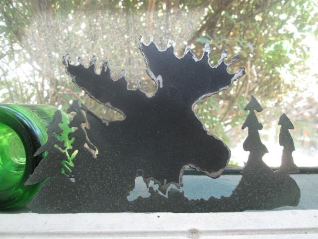
Came out pretty bad but learned a bit. The drag stand off doesn't quite work where your going over just cut areas. Pretty jagged and impossible to keep a fluid line. Across the bottom where fairly clean I just zipped across. Zero dross, edge actually round and smooth. Not the purpose for this machine but interesting. Too slow speed adds to dross and jagged edges. Just learning curve-practice practice.

Stuck it on machine-I'm sure I'll get some comments-but sort of an acknowledgement to Sean and the amount of effort he put into the group buy getting us these machines
- Addressing the ground clamp
Unscrewing to remove cable noted the shrink warp excessive, The eyelet not contacting either nut. Must have been grounding thru edge of hole. Simple, some trimming back of shrink tube needed. Though I ended up removing to inspect the crimped eyelet. Was Ok but re-staked anyway. Slipped over a long enough piece to cover cable where it passes thru handle. The hole in handle had already started cutting thru cable sheath as the punched hole in handle had a serious knife edge inside. Used round file to de burr.

Removed the bolt only to find the strap doesn't have ends, pinched under clamp ends. What the heck. Already close to edge so cant do anything with it. Next time at auto parts Ill pick up a 4"strap and replace. Funny how easily and fast unravels. Funnier are the off center nuts.
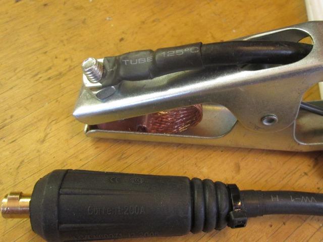
At the machine end nice connector, but as else where cable totally unrestrained. Outer rubber slides back, added some tube, zipped for now.
Unsure if Ill replace the cable just because of expense. In theory work lead needs to be longer, in practice seems the ground clamp is always the restricting issue, always tripping over it cause cant put where out of the way.
- Ground strap- ya know, flat braided wire with ends...
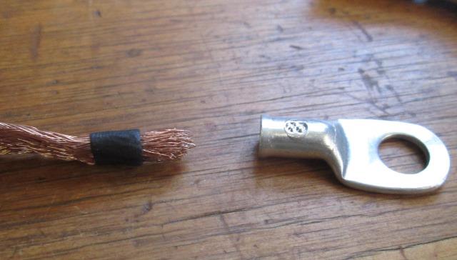
Drill out the riveted side of clamp to remove strap. Lightly formed one end of flat braided wire to insert into lug cup, slip over piece of shrink to hold. Tinned it then used torch to heat lug & partially fill with solder. Still heating insert end of wire. Let set a second. Cut off the shrink tube. Repeat for other end.

Wala-bout 4 1/2" center to center. Filed a relief one end of each of the clamp 'teeth' so that they will set flush, keep lug from turning but still clamp the lugs.

Reinstall using 5/16" brass bolt on the cable side, 1/4" on the opposite side. Because the 1/4" threads inside, pre trimmed 1/8" off the 1/4"x 1/2" long but got a little over zealous trimming so it will need replacing. Doing the 5/16" bolt afterwards.

Virtually full throat, before the strap was only about midway.

And fully open. Before I could only open an inch and strap was pulled tight right behind 'teeth'. Would have been short lived. Wont have to pay attention how hard I squeeze the handle or insert material. Silly ground clamp...who would have thought a manufacturer could screw up something so simple.
- Replacing added 20' cord with detachable 35' cord

Anyway, parts is parts. The 10amp/240v toggle switch is for torch trigger feed, adding a switch to disable. Having bad luck with recent Leviton stuff and local hardware was going to be almost $55, ordered off internet. Got a Superior Electric YGF169 flanged male twist lock receptacle for the machine and a YGA017F female twist lock for cord.[NEMA L6-30R & L6-30P]. Wall end of cord Ill reuse the junk Leviton 220v plug as mig is 120v. And the "new & improved" (35' length) of 10AWG SJOOW cord.

Started. Several things have happened to get to this point. First, as the connections to switch came out pretty sanitary and I don't know if useable on mig welder decided to cut cord about 2" outside of machine, easier than redoing. As it takes almost 2' of wire inside of machine this will give me a true 35' outside. It will decrease length if used on mig to Ý16' outside-still, twice and heavier than it has, project for another day. Used bolt cutters and whacked it off. Removed the strain relief and pulled cord inside.
What I wasn't sure about- If I had room inside for receptacle-I don't. Cut two donuts out of 1/2" PTF I had (cutting board) to make spacers. After removed most of the plumbing I started out with hole saw. Cutting thru case & existing cord hole was working but I was waiting for it to catch- stopped before disaster happened and used jig saw to finish. Thinking the whole time I have a plasma.
With screws loose thru receptacle flange and spacers in place removed one, used small drill bit thru flange & spacers to mark hole. Removed and drill clearance hole thru case. Did for all 3. Then I drilled thru completed assembly on case for 2 more.
Removed and wired. Sheer luck in that I just whacked the cable 2" outside of case instead of inside. Worked perfect. I thought I would need to trim of some more due to protrusion of receptacle but hadn't allowed for distance up to plug. Also allowed hooking up outside the case. Luck is good (this time).

The nutting & bolting spacing as I knew I couldn't get to bottom so rotated as shown. Having rotated for access, still, spent more time getting the lock washers and nuts started on the 2 screws toward the center of machine than everything else combined. Once started small open end wrench and got er tightened down-dabbed some nail polish on the nuts & threads.
Nice- move the plug from 20' cord to new 35' cord, install the new mating twist lock.

Just a lot more convenient having detachable cord-the extra length helps too! For grins I weighed cord- a little over 10#. Gained about 17' reach and cutter can store on the shelf.
- Add switch to disable torch trigger
Seems of all the tools I own that have double safety switches, that usually I remove or defeat, this is the 1st tool I've ever owned that wished it had one. Maybe a better torch down the road but for now....
Simple toggle switch on the case. The trigger wire just closes loop in 22 gage wire so cant be much power that activates cutting process. My switch way over kill. Placement...well there are a couple of places on face of cutter, easy to add switch, plenty of room, easy access.
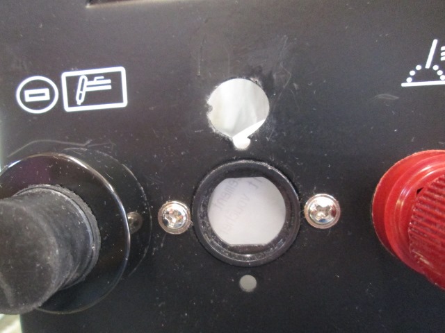
I decided I wanted directly over the trigger feed plug. Just seems like a logical place..about where that non meaningful symbol is. What is that? looks like garbage disposer blades? Between the Do Not Enter and Iwo Jima symbols.

However there's No room behind, access inside will be painful. Tried to convince myself to relocate, But no matter, that's where I want it...And why this got convoluted...
Directly behind and above trigger plug is a small circuit board [#2]. Its mounted on standoffs. Only one wire goes to & thru it then goes to cutters arc start lug [#1]. Its right where the added switch housing would be [#3}. Appears there's plenty of room to move it and standoffs or reorientation so doesn't it contact switch. As I cant tell what's where without switch installed I unplugged the board, removed it and the stand offs. Figure it out hopefully after installing switch.
Well...Gave some thought to the location of the board, just kind of odd where & how its mounted bugged me and couldn't continue. It could be that design is continuance of non arc start cutters and the space was there so it was simply used. But it occurred to me that its in the air path-just below the louvers out in free space. Which gives me pause on relocating at will. Decided, not knowing if it generates a lot of heat or other unknown reason, to keep the 'disks' of board in open space. If I just extend the stands offs about 3/4" should clear switch. It will require removal of the wire plug. Minor as its a simple board-wires can be soldered directly or, if I can, flip plug.
To get more room rotate the existing receptacle 90¯, gives me an additional 1/4"+ vertical space. Rotating new toggle switch can lower it gaining even more additional height. Re thinking give me about 1 1/4" verse 1/2" between top of new switch and bottom of existing main board. Plenty of room to reinsert the small board (once reworked) between. Ok, now were ready to install the switch
Think I have a clue what I'm doing (that's a joke) and not painting my self into a corner, redrilled to rotate the trigger plug. Then placed the switch hole. Switch stem is about Ä1/2", I drilled 7/16" hole. Then used mini files to open up leaving a small tang that will fit into slot on switch stem. This will keep switch from rotating. Note the hole DID end up off center to one side 1/8". Mostly because of the tang which I didn't allow for so hole center shifted. In my defense the picture is skewed, looks really off, the screws for plug are level.
I removed the receptacle after unplugging from board its wires go to. De soldered wire on receptacle I 'think' I is the power wire to torch switch. Since I'm doing thought not having energized wire in torch cable might be a good thing. As far as defeating torch switch doesn't really matter which side, its just a loop. If I mis-measured volt and think worth while Ill just swap wires on plug that goes to output of the source board. Soldered eyelet to removed wire and attached to new toggle. From toggle added another wire with eyelet and soldered to receptacle. Remounted receptacle and new toggle switch. Plugged back into board.

Simple. In case this isn't clear, a simple toggle switch inline on one wire going to torch handle switch. Now to reinstall the removed circuit board.

Well everything was going so swell. Got the plug removed and re soldered to opposite side of board that's being raised. To raise adding 6-32 x 1" screws with nuts. Re tapping metric stand offs for 6-32 got first one done. Second one almost done, got distracted, elbow hit drill press- I jerked -Snap. 1/2" of tap buried- not even trying. Off to the hardware. Was going to get another stand off, buy 2 more instead of using the screws but decided simpler would be to use 6-32 x 3" screws instead of adding to the 2" of stacked stands offs.

Ok- board reinstalled. The screws worked well as extended stand offs. Not that you can really see anything. Mile of room, all the wiring free and clear. Plugged in the new power cord-turn on breaker, power up machine- no smoke! Ran a few cuts, played with new toggle-everything still functions. Button her up-get some acetone and wipe of the stupid meaningless symbols from front of case.


- Accessing pilot arc points, secure cables

The pilot arc brass posts and points. The distance or gap between the posts controls pilot arc. Loosening the screws you can adjust the gap. Mine is working so though I don't need to adjust I happened to look at how the posts are attached to the board. They are screwed. IF down the road I need to adjust gap its likely loosening the screws that hold the contacts I might loosen the posts. If I managed to unscrew a post, means that bottom board would need to be removed to reattach. Hmmm.
It occurred to me if there were 2 holes thru bottom of case I could reattach or tighten posts if needed without removing the board. Since I have free time now that I might not later decided to remove the bottom board and drill access holes in case. Though the real motivation was if bottom was removed I could also drill some holes to zip tie the power cable and air lines to case bottom. The loose lines under the board really bugged me but didn't seem worth pulling apart-now I have justification...and some time to burn.
Removed the nuts from board stand offs. [NOTE: My machine hasn't been plugged in for a couple of weeks-still, short the points. Residual power MAY be present.] Unplugged all but 2 connections to bottom board, there are 2 in the middle that weren't easy to get to until board was slid out a bit. Removed board sliding out to the right side. Sticking a piece of masonite behind, just in case, drilled 2 3/8" holes thru case bottom. My measurements to accurately place the holes under the post mounting screws will be covered by the larger than needed 3/8" holes. Then drilled some 1/4" holes for zip ties.

And access holes.

Power cord and air line secured. And, if needed, access to the pilot arc post mounting screws. Will not make getting to or adjusting the points any easier but if post become loose wont need to remove the circuit board to re tighten. Since I had the board out I readjusted the points to .035 gap.

Not a tool I use often, but when used makes task a breeze. This cutting out center section of seat base, just zipped it out.
Back to Our shops tool mods section